In order to solve the problems of low precision, disturbance and unsmooth movement of heavy-duty long manipulator in working conditions, an IPSMC (improved power sliding mode control) based on force impedance control is proposed. First, the robot is organized and an accurate kinematics model is established and the motion characteristics of special manipulator system are analyzed. Combined with the dynamic model, the deviation of the position and velocity feedback from the expected value is converted by the force impedance controller, which makes the manipulator more flexible under the condition of low damping. At the same time, according to the position and speed feedback, an IPSMC is proposed, which uses the sliding mode control (SMC) to reduce the disturbance and oscillation in the working condition, so as to realize the control in the position space and the control in the force space. Finally, through Adams-Simulink co-simulation, the designed control system is tested. The results show that the force/position hybrid control strategy has good anti-interference ability for the long manipulator with large working range. While improving the flexibility of the manipulator, it also weakens the end chattering problem to some extent, enhances the robustness of the control system, and meets the requirements of working conditions.
Keywords
heavy-duty long manipulator
force impedance control
power reaching law
SMC
force/position hybrid control
Author information
Introduction
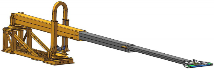
With the rapid development of robot technology, common industrial robots are unable to meet few specific working situations, such as the working environment with large working range or large load capacity, while long telescopic manipulator and heavy load manipulator can be used as a part of special robots, which play an important role in logistics palletizing, industrial processing, space service and so on [1]. The research object of this paper is a self-developed special heavy-duty long manipulator, which is currently used in the palletizing and loading robot (figure 1). This robot is used for palletizing and loading heavy goods in medium and large logistics warehouses. Therefore, its Cartesian space and load capacity are larger than those of ordinary robots. In order to meet its performance requirements, its rigid long arm and heavy load characteristics inevitably lead to low precision of its end-effector and disturbance of its large arm, which has the potential risk of damage to the goods loaded on the pallet and affects the loading efficiency. Scholars at home and abroad have put forward corresponding control technologies to solve similar problems.
Figure 1.
Three-dimensional model diagram of heavy-duty long manipulator.
Barjuei [2] designed a hybrid force/position control strategy based on joint acceleration and time evolution for equivalent rigid lever system and finite element discrete robot system. This hybrid control strategy can make the manipulator control the position space and force space according to its own situation, so as to meet the performance requirements of the joint in a certain space. Scholars use proportional–integral–derivative (PID) controller to track the position control, and simplify the rigid dynamic model to estimate the angular acceleration and torque of the joint in the force control law, and change the reference position input by the position controller according to the direction and amplitude of the external force, so as to achieve good trajectory tracking and external force adjustment. Ma et al. [3] put forward an implicit hybrid force impedance control method based on position. Scholars used the force control method with positive position feedback and combined it with impedance control to establish a strong and high stiffness model, which made the end-effector have fast response and high resolution characteristics in position and force control.
Manipulator is a complex system with strong coupling and nonlinearity. Sliding mode control (SMC) is widely used in the field of robot engineering because of its good anti-interference, matching uncertainty and strong robustness to parameter disturbance [4]. At the same time, the SMC can further improve the working accuracy of the manipulator system. The switching hyperplane of the system is designed according to the desired ideal characteristics of the system. The actual state of the system is converged from the hyperplane to the hyperplane through the sliding mode controller. Until the system reaches the switching hyperplane, the controller slides the system along the hyperplane to the origin of the system to control the error [5]. Gracia [6] and others put forward an adaptive SMC algorithm based on force feedback, which can track the uncertain disturbance of the manipulator due to the change of material stiffness. Liu [7] put forward PASMC (proposed adaptive SMC) to solve the tracking accuracy of mobile manipulator, and designed an adaptive sliding mode control law by time-delay control (TDC) and common sliding mode control law. Zhao et al. [8], aiming at the problems of convergence speed and high-frequency chattering of the robot’s trajectory tracking, designed a hybrid double-power reaching law by using the advantages and disadvantages of two types of sliding mode reaching laws, namely, saturation function and hyperbolic tangent function. Experiments have proved that the designed control law can improve the convergence speed of the system and effectively control the robustness of the system. Yue et al. [9] put forward a new multi-power reaching law to solve the problems of chattering and slow convergence speed of traditional SMC system, which uses multiple power terms to adjust the reaching rate of different states of the system, so as to improve the convergence speed of the system and reduce the steady-state error.
In view of the above, based on the tracking control algorithm of force impedance control, this paper proposes an IPSMC force/position hybrid control strategy to weaken the oscillation problem of heavy-duty long manipulator. In this paper, the research object is a novel structure. Firstly, the kinematics model is established, and the dynamics and their characteristics are obtained. Secondly, the force impedance control strategy is adopted, so that the manipulator can still make the expected force due to the change of the environment, and produce the compliant movement that keeps good contact with the environment. Then, aiming at the sliding mode variable structure control in the position space, an IPSMC is designed, which forms a force/position hybrid controller with the feedforward control in the force space. Lyapunov proves that the controller designed in this paper is asymptotically convergent and stable. Finally, simulation and experiment are carried out in the software toolbox [10], and a good effect of the end-effector position trajectory is obtained. The simulation results verify the effectiveness of the proposed compliant control strategy.
Dynamic
Kinematics
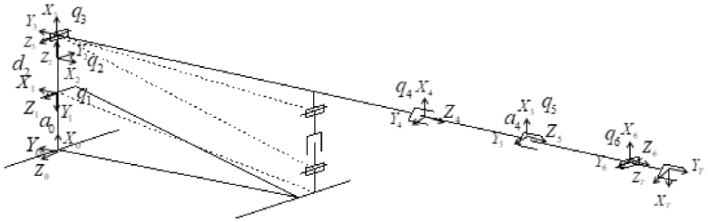
FK (Forward kinematics) refers to the angle or offset of each joint in the joint space, and the end pose of the manipulator in the Cartesian space can be obtained by algorithm. In this paper, the main chain joint type of heavy-duty long manipulator is PRRPPR (P stands for prismatic joint and R stands for revolute joint). The joint diagram of the manipulator is shown in figure 2, and the coordinate system is established from the base frame. For the convenience of calculation, the Z axis of the base frame is aligned with the Z axis of the first prismatic joint. According to the modified Denavit–Hartenberg (D–H) method, the homogeneous coordinate system is established and parameters are shown in figure 2 and Table 1 [11, 12].
Figure 2.
Establishment of D–H coordinate system model of manipulator.
i
𝛼i−1 (°)
ai−1 (mm)
di (mm)
𝜃i (°)
qi initial
qi range
1
0°
a0 = 1392
q1
90°
0
(0, 650)
2
90°
0
d2 = 904
q2
180°
(175°, 185°)
3
90°
0
0
q3
−90°
( −100°, −80°)
4
90°
0
q4
0°
420
(420, 7020)
5
0°
a4 = 31
q5
0°
10 164.85
(10 164.85, 14 196)
6
−90°
0
0
q6
−90°
( −92°, −88°)
T
0
a6 = 1308
0
−90°
Table 1
Parameters of D–H coordinate system of manipulator.
Substituting the parameters of each joint link in the D–H table into each homogeneous transformation matrix, the pose of the coordinate system at the end of the manipulator relative to the base coordinate system can be obtained as follows:
where qij = qi + qj, s and c are the abbreviations of sine and cosine functions, respectively, and 𝛼i, ai−1, di and 𝜃i are the twist angle, length, offset and joint angle of the connecting rod in D–H model parameters, respectively.
IK (Inverse kinematics) solves the joint variables under the condition of determining the end pose information, and take them as the control input variables of each link of the manipulator system. Since the numerical solution needs a lot of recursive calculations, and the solution time is relatively long, numerical solutions are rarely used to solve IK in practical work. According to the structural characteristics of the research object in this paper (figure 2), the joint variables are obtained with the end pose relationship as shown in equation (1). Joint variables can be solved by algebraic method:
The joint variables q4 and q5 are two-stage telescopic arms, which are driven by the tooth drive at the same time, so they are equal changes:
where x = px − a0 − d2 and .
Similarly:
At the same time, the velocity Jacobian reflects the relationship between the motion velocity of manipulator Cartesian space and the motion velocity of joint space [13], so it can control the velocity of robot Cartesian space. The number of columns of Jacobian matrix is the number of joints of the manipulator. As joint 4 and joint 5 are essentially long telescopic joints, the pseudo-inverse Jacobian matrix is [14]:
Therefore, for the conversion of joint velocity and acceleration between Cartesian space and joint space, there are the following relationships:
The establishment of kinematics and Jacobian matrix of manipulator lays the foundation for dynamic model and control model in Cartesian space.
Dynamic model
Manipulator control often performs tasks in the Cartesian space [15], so the dynamic model can be expressed in the Cartesian space by borrowing the relations (8) and (9) of Jacobian matrix in kinematics [16]:
where
where D (q) is the inertia matrix of the manipulator, is the centrifugal force and Coriolis force matrix, G (q) is the gravity term, fv is the viscous friction coefficient, fs is the static friction coefficient, 𝜏 is the input control torque of the manipulator in the joint space, and q, , are the joint variables, velocity and acceleration of the manipulator in the joint space, respectively. , is the joint velocity and acceleration in the Cartesian space of the manipulator, and Fx is the contact force of the end-effector in the Cartesian space. Equation (10) reflects the relationship between the joint variables, velocity and acceleration and the end contact force in the Cartesian space, considering the friction force.
The dynamic model of manipulator in Cartesian space has two properties:
Inertia matrix Dx(q) is a positive definite matrix, symmetrical and bounded.
Matrix is skew symmetric, that is, any vector 𝜒 satisfies:
In this paper, the controller is designed according to the dynamic model of manipulator Cartesian space, and the force/position hybrid control based on force impedance sliding mode is realized.
Force/position hybrid controller
Force-based impedance controller
In this paper, impedance control is used to improve the compliant motion of the end of the manipulator [17]. Impedance control is to regard the tool and environment at the end of the manipulator as a mass-spring-damping system, and the impedance controller as a mechanical impedance. It controls the force by adjusting the dynamic relationship between the position of the end of the manipulator and the force, reducing the tracking error caused by the position control system [18], and realizes indirect force control. The following impedance control model is adopted in this paper:
where Md, Bd, Kd represents inertia matrix, damping matrix and stiffness matrix respectively. xe, , respectively represent the actual position, velocity and acceleration of the end-effector of the manipulator in Cartesian space. xd, , , respectively, correspond to the expected position, speed and acceleration. Equation Ef is defined as the deviation Ef = FI − Fe between the expected contact force FI and the actual contact force Fe of the force impedance.
The force deviation is taken into account in the impedance control model to realize force tracking, and the equation (12) contains the position deviation Ex = xd − xe. Laplace transform is performed on both of them to obtain the expected impedance equation in the frequency domain:
It can be seen from the above formula that, because all Md, Bd, Kd are diagonal matrices, the target impedance model and environment x, y, z are not coupled in the direction. When the end-effector comes in contact with the goods, the obtained actual position xe forms a position deviation Ex with the expected trajectory position xd. After setting the impedance control parameters, the position deviation of the trajectory is converted into a force deviation Ef, and the actual contact force Fe at the end of the manipulator compensates for the force deviation, so that the expected contact force FI with compliance is obtained, and the force impedance control is realized.
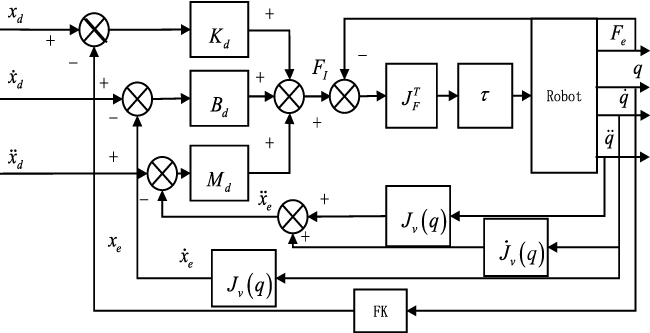
As shown in figure 3, a force-based impedance control strategy is composed of an impedance outer loop and a force feedback inner loop. The inner loop is fed back by the contact force at the end of the manipulator, and the expected impedance contact force forms the joint driving input torque. In the outer loop control loop, the manipulator feeds back the position, velocity and acceleration of the joint trajectory, and the Jacobian matrix and its derivatives are used for forward kinematics transformation. The impedance control law converts the position deviation into the force deviation. This makes it difficult for the manipulator to show high stiffness, and makes the rigid system more flexible with low damping and stiffness, which reduces the actual contact force with the environment and the disturbance amplitude at the end of the manipulator. Considering that the manipulator carries heavy loads of goods, it needs active power control to slow down the vibration caused by the relationship between heavy loads and long arms, so that the manipulator can adjust its impedance characteristics to better contact with the loading environment, so the impedance control strategy based on force is selected.
Figure 3.
Impedance control based on force.
IPSMC
Due to the change of load quantity and size in the work of manipulator, the unique structure of the system in itself has some nonlinear uncertain factors [19] such as dynamics and high-low frequency unmodeled dynamics of structural resonance mode, which make the system appear to have disturbance and chattering problems. The single force control or position control strategy cannot meet the working requirements of this special manipulator, and when there is a small position deviation at the end of the manipulator, it is easy to cause a large contact force, which is not conducive to the efficient completion of the task. As the sliding mode variable structure control has nothing to do with the perturbation of the system parameters, its system structure changes with time, and it has switching characteristics. SMC is helpful to solve the stability of the nonlinear system, has good robustness to the disturbance generated in the system, and has fast convergence speed and strong anti-interference [19, 20].
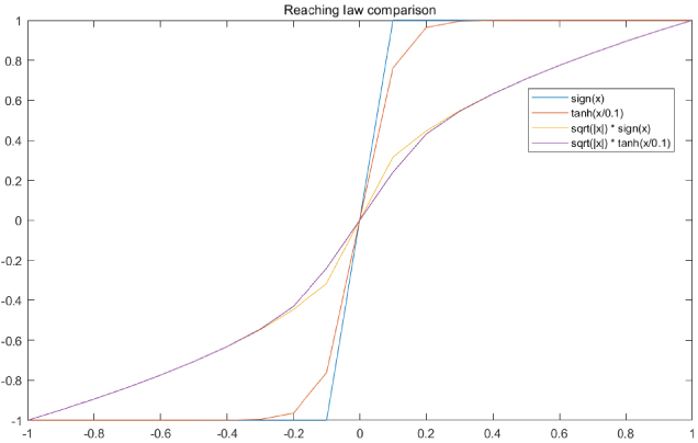
Step function is often used as switching function in designing controller. In the actual control process of manipulator, the switching of this function lags behind the motion state of the controlled object. At the same time, because of its discontinuity, when the system approaches the designed switching surface, the controller will be subject to oscillation and chattering due to the lag error. The power reaching law can enter the sliding mode surface more smoothly than the exponential reaching law, that is, effectively weaken the chattering problem, but its speed is slower. Therefore, this paper proposes an improved mixed power reaching law on the SMC, constructs a mixed power reaching law with special power function and hyperbolic tangent function, and adjusts it by using parameters, so as to give full play to the respective characteristics of fast convergence of exponential reaching law and weakening chattering of power reaching law.
Tracking error is defined as:
formula 𝛬 is a positive definite matrix. 𝛿(t), , respectively represent the ideal position, velocity and acceleration of the end-effector of the manipulator in Cartesian space. e (t), , represent the expected and actual position, velocity and acceleration errors, respectively of the manipulator end-effector in Cartesian space.
The existence condition is the premise of the application of sliding mode variable structure control. If the initial point x (0) of the system is not near s = 0, but at any position in the state space, it is required that the motion of the system must tend to the switching surface s = 0, otherwise the sliding mode motion cannot be started. Existence conditions are:
Sliding surface is defined as:
In order to reduce chattering and increase the approaching rate of sliding surface, aiming at one nonlinear function fal(x, 𝛼, 𝛿) [21], another nonlinear function is defined as:
where, exponent of power function is 𝛼1 > 0, 𝛼2 > 0 and 𝜑 is the steepness of hyperbolic tangent function. The interval length of positive and negative symmetric line segment of function nfal(s, 𝛼1, 𝛼2, 𝜇) near the origin is 0 < 𝜇 < 1. The steepness of power function is 0 < 𝜑 < 0.5. s is the sliding mode function, and when the sliding mode function is less than the interval length, that is, |s| < 𝜇, the sliding mode independent variable gain 𝜇𝛼1−1 is smaller, otherwise, the gain is larger.
The design of switching function has great influence on chattering and approaching rate. Compared with the common approach law of step function in figure 4, when the system state is far away from the sliding surface, the power switching function can speed up the movement speed, while when it is near the sliding surface, the movement speed will slow down correspondingly, and the system will be smoother near the switching surface, thus reducing the movement time of crossing the sliding surface back and forth and reducing the chattering during switching.
Figure 4.
Impedance control based on force
Take the following IPSMC:
where 𝛽1 > 0, 𝛽2 > 0 is a positive odd number. k1 > 0, k2 > 0. 𝜀 is the convergence rate of the reaching law. When |s| < 𝜇 sliding mode system approaches the equilibrium point, i.e., s → 0, sliding mode reaching law is dominated by s𝜇𝛼1−1. At this time, the approaching speed of nfal(s, 𝛼1, 𝛼2, 𝜇) gradually increases. Since there is a continuous and smooth power function term near the zero point, the high steepness of the power function can ensure that the control system can quickly reach the sliding mode surface. Compared with the switch of the step function, the step function is more abrupt and discontinuous at the turning point. When |s| > 𝜇, the function of is smoother than that of and sign(x), especially at ±𝜑. Therefore, by combining the convergence rate of 𝜀 and k1|s|𝛽1 sign(s) + k2|s|𝛽2 with high specific gravity, the former can reduce the problem of high-frequency vibration, while the latter can achieve the effect of stable input and signal amplitude, and can still ensure a large speed approaching the sliding mode.
Combined with the local arrival condition equation (16), the moving point reaches the switching surface field in a finite time, and the following expression is given as:
In equation (20), 𝜀 > 0, k1 > 0, k2 > 0, 𝛽1 > 0, 𝛽2 > 0, 𝛼1 > 0, 𝛼2 > 0, 0 < 𝜇 < 1, when s → 0+, −𝜀 nfal(s, 𝛼1, 𝛼2, 𝜇) − k1|s|𝛽1 sign(s) − k2|s|𝛽2 < 0, so , and similarly, when s → 0−, .
On the other hand, it can take the equivalent form of general arrival condition:
The switching function satisfies the following conditions: ① differentiable; ② crossing the origin. Since the state variable can take any value, that is, it can be far away from the switching surface, equation (21) is the global arrival condition, and Lyapunov is assumed:
The establishment of equation (22) means that the system will eventually reach and remain on the sliding mode switching surface, including:
From the above parameters, it can be seen that satisfies the reaching condition of sliding mode.
In the position space, the position deviation is formed by the actual position of the terminal and its velocity feedback, and the velocity Jacobian matrix and the expected value. The IPSMC and the force impedance controller are used to realize the position control law:
where 𝜀 > 0, k1 > 0, k2 > 0.
In the direction of force control, compensation force control is carried out through expected force feedforward control and feedback of actual force difference:
And through the selection matrix S, the driving joints are selectively controlled to realize the force/position hybrid control strategy:
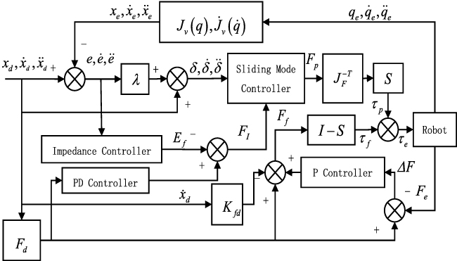
The impedance-based sliding mode force/position hybrid control structure of the manipulator is shown in figure 5.
Figure 5.
Structure diagram of sliding mode force/position hybrid controller based on impedance.
Stability analysis
According to reference [22], for arbitrary 𝜑 > 0 and arbitrary real numbers x, the following inequalities are obtained:
where 𝜎 = 0.2785.
According to literature [23], for , when 𝜁, V (t):[0, ∞) → R, 𝛼 > 0, there is:
The following transformations are possible for function :
As , evidently .
Substituting the controller (24) into the dynamic equation (10) to obtain the control law:
where , , is the friction matrix.
Defining Lyapunov function as , and knowing that V ≥ 0 according to properties 1 and 2, then:
When |s| < 𝜇:
Because 𝛽1, 𝛽2 > 0 is a positive odd number. 𝜀 > 0, 𝛼1 > 0, 0 < 𝜇 < 1, k1, k2 > 0. can be guaranteed.
K = k1 + k2 among them. 𝜆min(K) and 𝜆max(Dx) are the maximum and minimum eigenvalues of coefficient matrix and inertia matrix, respectively, and let . According to Lemma 2, the inequality is further obtained:
Evidently: , the derivative of the system error converges gradually, i.e., the tracking error e and sliding mode s of the system are consistent and finally bounded, and the proof is complete.
It can be inferred that the controller designed in this study is stable based on Lyapunov stability theorem. When |s| > 𝜇, the convergence accuracy of Lyapunov function is determined by each parameter in , specifically by steepness 𝜑, linear term 𝜀 and the ratio of coefficient to eigenvalue of inertia matrix. When the steepness of the power function is smaller, the linear term is smaller and the coefficient matrix is larger, the convergence effect of the system is better.
Experiment and simulation
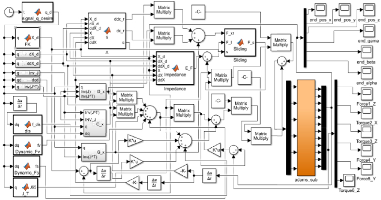
The 3D model of the manipulator established by SolidWorks platform is imported into Adams, and the material properties and driving joints are added according to the actual requirements, so that the model can be dynamically simulated. Then, the united simulation of Adams and Matlab/Simulink is realized through the control system interface (figure 6), and the control simulation model is built in Simulink environment.
Figure 6.
Adams-Simulink control system model.
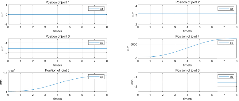
In order to simulate the movement path of the loading task of the manipulator, the robotics toolbox is used to plan the movement of each joint of the manipulator. The initial position of the joint is , and target location is . A quintic polynomial is used to plan the trajectory to get the position change of each joint (figure 7) and the trajectory of the end-effector in Cartesian space (figure 8):
Figure 7.
Track of joint position.
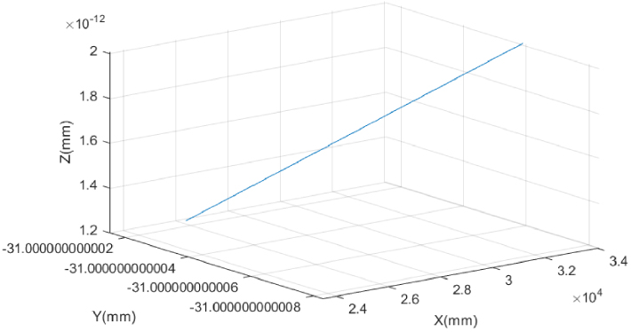
Figure 8.
Trajectory of end-effector in Cartesian space.
At the same time, in order to verify the effectiveness of the above control strategy, 4000N concentrated load is added to the end of the manipulator in Adams as the load test of carrying goods, assuming that the unknown disturbance to the manipulator is fdis = 10 sign. After the viscous friction coefficient fv = 0.1 and static friction coefficient fs = 0.5 are set in Adams, the desired trajectory qd = [0. 2t3, 0.1° sin t, 0.1° cos t, 7t3, 7t3, 0.005° t3]T of the joint is designed, Md = 1, Bd = 100, Kd = 400, are the impedance control parameters and the sliding mode controller parameters of controller are 𝛬 = 0.0001, A = 40, 𝜑 = 0.1 and 𝜀 = 35, 𝛼1 = 0.25, 𝛼2 = 0.5, 𝜇 = 0.01, k1 = 5, k2 = 5, 𝛽1 = 3, 𝛽2 = 2 for the experiment.
Figure 8 shows the movement trajectory of the end-effector of the manipulator in Cartesian space with reference to the base coordinate system of the manipulator. In force space, only the driving joints 1, 2 and 6 are controlled by force, and the other driving joints are controlled by the IPSMC based on impedance. The experimental results compare the improved sliding mode force/position hybrid controller based on impedance proposed in this paper with the sliding mode controller with step function as switching function and common power function.
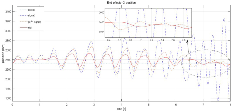
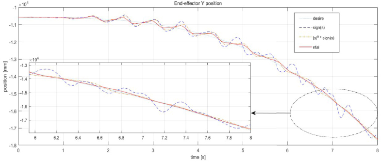
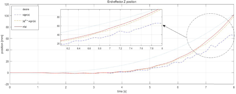
Figures 9–11 respectively show the response curves of the position of the end-effector in XYZ when the manipulator system carries heavy objects. It can be seen that the power reaching law obviously reduces most of the chattering compared with the SMC with the step function as the switching function, and the amplitude of chattering is also relatively reduced. Compared with the step function, the common power sliding mode reaching law also reduces most of the chattering. After 4 s, when the extension of the two-stage telescopic arm of the manipulator begins to exceed half of the measuring range, the coupling vibration effect of the rigid long arm gradually appears, that is, the excessive extension makes the end of the load-bearing object disturb and shake when moving. In figure 9, in the X direction, it is difficult for the common SMC law to reduce chattering. In contrast, the characteristic of IPSMC law can be reflected at the time of 6 s, and the control law can speed up the sliding mode movement when the system state is gradually away from the sliding mode surface. On the other hand, it also makes the system quickly track the desired state; combined with the smoothness and continuity of the hyperbolic tangent function, the frequency and amplitude of the terminal oscillation are further reduced, and the tracking accuracy is improved by 30%, although there is still an permitted error of 1–2 cm from the expected trajectory. The power control law can improve the tracking accuracy by 30%–40% in the Y direction (the telescopic direction of the manipulator) and the Z direction (the swinging direction of the manipulator). When loading goods, the tail end moves up and down inside the carriage, and the weight carried by the tail end retracts, and in turn, retracts the manipulator of the parent joint, which is of course one of the manifestations of chattering. Therefore, the ability to reduce micro-chattering in the Y direction can make the manipulator work more stably, and the fluctuation of the control law proposed in figure 10 is more gentle, and the tail end can be controlled within the tracking error range of about 5 cm. In the Z direction, the trajectory of IPSMC is smoother. Because the displacement of the joint itself is relatively small, the error caused by it can be tracked quickly, so the fluctuation caused by it is relatively small, and the expected trajectory can be tracked quickly. Finally, the error is controlled within 1 cm.
Figure 9.
The end-effector position of X.
Figure 10.
The end-effector position of Y.
Figure 11.
The end-effector position of Z.
The comprehensive experimental results show that the IPSMC based on impedance proposed in this paper can improve the tracking ability of the manipulator system with long stroke and heavy load. It weakens most of the high-frequency oscillations and reduces the amplitude of most of the low-frequency oscillations. When the system is far away from the sliding surface, the control law speeds up the sliding mode movement and makes the system enter the sliding surface faster. Moreover, the sliding surfaces can be switched quickly to ensure the stability of the system, which can meet the performance requirements of the special manipulator for large-scale heavy-duty transportation. At the same time, as can be seen from figure 9, in the X direction opposite to the center of gravity of the end weight in Cartesian space, the error between the expected position and the actual position is converted into force deviation in Cartesian space by force impedance control, and then the corresponding joint force and moment are compensated, so that the manipulator has the characteristics of low damping and low rigidity, reduces the disturbance amplitude of the end-effector, and enhances the flexibility of the high-rigidity manipulator system. Compared with the large working range of special manipulator, the designed controller can meet its position tracking accuracy requirements and has good robustness, which proves that the proposed control strategy can effectively improve the dynamic response performance of the system.
Conclusion
Aimed at the problem of precision control and disturbance of heavy-duty long manipulator system, this paper presents an SMC based manipulator with adaptive characteristics. In order to improve the robustness of manipulator system, avoid disturbance and reduce the control precision, this paper designs an improved sliding mode force/position hybrid control strategy based on impedance. For the special manipulator with this special structure, the kinematics model is first established to plan the trajectory of the manipulator, and Jacobian matrix paves the way for the dynamics model and control strategy. Then, the rigid body dynamics model of the manipulator considering friction force is established, and the impedance control model based on force is analyzed to realize the force impedance control strategy in Cartesian space. Following this, the switching function of the SMC is analyzed and selected. Aiming at the fact that the step function cannot eliminate the oscillation when the sliding mode surface is switched in the controller, an improved reaching law of the IPSMC is designed by combining the characteristics of the continuous hyperbolic tangent function and the power function to effectively reduce the vibration amplitude and jitter frequency of the tool at the end of the long arm, and then establish Lyapunov function for the stability analysis of the controller. Finally, through Adams-Simulink united simulation, the shipping experiment under the heavy load environment is carried out. The experiment shows that the IPSMC with smooth characteristics can effectively reduce the disturbance of the manipulator when it works, and can compensate the input deviation of the system by combining the force impedance control strategy. Improving the damping characteristics of the low stiffness of the manipulator system can, to a certain extent, make the output torque of the end joint of the manipulator relatively weaken the chattering problem caused by heavy loading. Experiments also prove that the proposed control strategy can improve the flexibility problems such as low precision and disturbance of the manipulator, enhance the anti-interference and quick response ability of the manipulator system, improve its dynamic performance, and meet the needs of large-scale heavy-duty handling.
Conflict of interest
The authors declare no conflict of interest.
Funding
Innovation School Project of Education Department of Guangdong Province, China (Grant no. 2020KTSCX097, 2021ZDZX1020).
Tertiary Education Scientific research project of Guangzhou Municipal Education Bureau (Grant no. 202235237).
References
1.
ZhangY, DingW, DengH. Reduced dynamic modeling for heavy-duty hydraulic manipulators with multi-closed-loop mechanisms. IEEE Access. 2020;8: 101708–101720.
2.
BarjueiES. Hybrid position/force control of a spatial compliant mechanism. Int J Automotive Mech Eng. 2017;14(3):4531–4541.
3.
MaZ, PooA-N, AngMH, HongG-S, SeeH-H. Design and control of an end-effector for industrial finishing applications. Robot Comput-Integr Manuf. 2018;53: 240–253.
4.
GeY. Research on robot manipulators trajectory tracking control based on adaptive sliding mode control. Shenyang, China: Shenyang University of Technology; 2019.
5.
KangOR, KimJH. A new approach to sliding mode control of a robot system with its computed torque treatment. In: 2021 21st International Conference on Control, Automation and Systems (ICCAS). 2021. p. 1064–1068.
6.
Ernesto SolanesJ, GraciaL, Munoz-BenaventP, Valls MiroJ, GirbésV, TorneroJ. Human-robot cooperation for robust surface treatment using non-conventional sliding mode control. ISA Trans. 2018;80: 528–541.
7.
HesongL, WenxuY, HongyuN, PengL. Sliding mode control of inspection manipulator based on new adaptive law. Control Eng China. 2021;1–10. doi:10.14107/j.cnki.kzgc.20210423.
8.
KaixuanZ, ShuboW, DongwuL. Sliding mode control of manipulator based on improved reaching law. Control Eng China. 2021;1–7. doi:10.14107/j.cnki.kzgc.20210091.
9.
YueC, YuH, MengX. Decoupled sliding mode control for underactuated systems based on novel reaching law. Control Eng China. 2021;18(6):1–6.
10.
WangC, ZhangW, JiangJ, YeX, JiangL. Simulation of kinematics analysis and control of industrial welding six-joints robot based on Matlab/Adams. Chinese J Construcution Machinery. 2020;18(6):6.
11.
ZhangT, YuY, ZouY. An adaptive sliding-mode iterative constant-force control method for robotic belt grinding based on a one-dimensional force sensor. Sensors. 2019;19(7):1635.
12.
SinghA, SinglaA. Kinematic modeling of robotic manipulators. Proc Natl Acad Sci India. 2017;87(3):303–319.
13.
NarayanJ, AbbasM, DwivedySK. Transpose Jacobian control of flexible joint upper limb exoskeleton system. In: Machines, mechanism and robotics. Cham: Springer; 2022. p. 401–411.
14.
SingletaryA, KolathayaS, AmesAD. Safety-critical kinematic control of robotic systems. IEEE Control Syst Lett. 2022;6: 139–144.
15.
YunJT, SunY, LiCQ, JiangD, TaoB, LiG, Self-adjusting force/bit blending control based on quantitative factor-scale factor fuzzy-PID bit control. Alexandria Eng J. 2022;61(6):4389–4397.
16.
DaiJ, ZhangY, DengH. Novel voltage-based weighted hybrid force/position control for redundant robot manipulators. Electronics. 2022;11(2):179.
17.
LiuG, HanB. Improving robotic impedance control performance employing a cascaded controller based on virtual dynamics model. Proc Inst Mech Eng Part C: J Mech Eng Sci. 2022;236(3):1815–1825.
18.
LiH, WangF, XuS, HouY, LuS. Compliance control of end-effector of space manipulator based on impedance control. Aerospace Control Appl. 2019;45(1):7.
19.
JiP, LiC, MaF. Sliding mode control of manipulator based on improved reaching law and sliding surface. Mathematics. 2022;10(11):1935.
20.
SunC. Research on trajectory planning and control of manipulator. Baotou, China: Inner Mongolia University of Science and Technology; 2020.
21.
HanJ. Active disturbance rejection control technique–the technique for estimating and compensating the uncertainties. Beijing, China: National Defence Industry Press; 2008.
22.
PolycarpouMM, IoannouPA. A robust adaptive nonlinear control design. Automatica. 1996;32(3):423–427.
23.
JohansenTA, IoannouPA. Robust adaptive control of minimum phase non-linear systems. Int J Adapt Control Signal Process. 1996;10(1):61–78.