


1. Introduction
Carbon nanotubes (CNTs), a fascinating material with outstanding properties has inspired the scientist, engineer and technologist for wide range of potential applications in many areas [1]. Since all these properties are concerned directly to the atomic structure of nanotubes, it is quite necessary to have a thorough understanding of the phenomenon to control nanotube size, the number of shells (walls), the helicities and the structure during growth. The full potential of nanotubes for applications will not be realized until the structure of nanotubes during their growth is optimized and well controlled. For utilization of CNTs properties in real world applications, like composite preparation, it is desired to obtain high quality and in bulk quantity using growth methods that are simple, efficient and inexpensive. Significant work has been carried out in this field and various methods have been studied to synthesize CNTs by several researchers.
2. Properties
Carbon nanotubes are endowed with exceptionally high material properties, very close to their theoretical limits, such as electrical and thermal conductivity, strength, stiffness, toughness and low density.
2.1. Mechanical properties of CNTs
The strength of C-C bond gives a large interest in mechanical properties of nanotubes. Theoretically, these should be stiffer than any other known substance. Young's modulus of the single walled carbon nanotubes (SWCNTs) can be as high as 2.8-3.6 TPa and 1.7-2.4 TPa for multiwalled carbon nanotubes (MWCNTs) [2]which is approximately 10 times higher than steel, the strongest metallic alloy known. Experimental values of Young’s modulus for SWCNTs are reported as high as to 1470 GPa and 950 GPa [3, 4] for MWCNTs, nearly 5 times of steel. There are no direct mechanical testing experiments that can be done on individual nanotubes (nanoscopic specimens) to determine directly their axial strength. However, the indirect experiments like AFM provide a brief view of the mechanical properties as well as scanning probe techniques that can manipulate individual nanotubes, have provide some basic answers to the mechanical behavior of the nanotubes [5]. The analysis performed on several MWCNTs gave average Young’s modulus values of 1.8 TPa, which is higher than the in – plane modulus for single crystal graphite. So the high stiffness and strength combined with low density implies that nanotubes could serve as ideal reinforcement in composite materials and provide them great potential in applications such as aerospace and other military applications.
2.2. Electrical properties of CNTs
The nanometer dimensions of CNTs, together with the unique electronic structure of a graphene sheet, make the electronic properties of these one-dimensional (1D) structures extraordinary. The one dimensional structure of CNTs helps them in making a good electric conductor. In a 3D conductor the possibility of scattering of electrons is large as these can scatter at any angle. Especially notable is the fact that SWCNTs can be metallic or semiconducting depending on their structure and their band gap can vary from zero to about 2 eV, whereas MWCNTs are zero-gap metals. Thus, some nanotubes have conductivities higher than that of copper, while others behave more like silicon. Theoretically, metallic nanotubes having electrical conductivity of 105 to 106 S/m can carry an electric current density of 4 × 10⁹ A/cm2 which is more than 1000 times greater than copper metal and hence can be used as fine electron gun for low weight displays. Due to the large diameter of MWCNTs, their transport properties approaches those of turbostatic graphite. Theoretical study also shows that in case of MWCNTs the overall behavior is determined by the electronic properties of the external shell. Conductivities of individual MWCNTs have been reported to range between 20 and 2 × 10⁷ S/m [6], depending on the helicities of the outermost shells or the presence of defects [7].The electronic properties of larger diameter MWCNTs approach those of graphite. Nanotubes have been shown to be superconducting at low temperatures. As probably CNTs are not perfect at ends and end defects like pentagons or heptagons are found to modify the electronic properties of these nanosystems drastically. There is great interest in the possibility of constructing nanoscale electronic devices from nanotubes and some progress is being made in this area. SWCNTs have been recently used to form conducting and semiconducting layers (source, drain and gate electrodes) in thin films transistors. So the high electrical conductivity of CNTs makes them an excellent additive to impart electrical conductivity in otherwise insulating polymers. Their high aspect ratio means that a very low loading is needed to form a connecting network in a polymer compared to make them conducting.
2.3. Thermal properties of CNTs
CNTs are expected to be very good thermal conductors along the tube, but good insulators laterally to the tube axis. Experiments on individual tubes are extremely difficult but measurements show that a SWCNT has a room-temperature thermal conductivity along its axis of about 3500 W m−1 K−1 and MWCNTs have a peak value of ~ 3000 W m−1 K−1 at 320 K; compare this to copper, a metal well-known for its good thermal conductivity, which transmits 385 W m−1 K−1 [8]. Although for bulk MWCNTs foils, thermal conductivity limits to 20 W m−1 K−1 suggesting that thermally opaque junctions between tubes severely limit the large scale diffusion of phonons. The thermal conductivity of CNTs across axis (in the radial direction) is about 1.52 W m−1 K−1, which is about as thermally conductive as soil. Both SWCNT and MWCNT materials and composites are being actively studied for thermal management applications, either as “heat pipes” or as an alternative to metallic addition to low thermal conductive materials. In case of composites, the important limiting factors are quality of dispersion and interphase thermal barriers.
3. Synthesis of CNTs
A variety of synthesis methods now exist to produce carbon nanotubes. The three main production methods used for synthesis of CNTs are d.c. arc discharge, laser ablation and chemical vapor deposition (CVD).
3.1. d.c. arc discharge technique
The carbon arc discharge method, initially used for producing C60 fullerenes, is the most common and perhaps easiest way to produce carbon nanotubes as it is rather simple to undertake. In this method two carbon rods placed end to end, separated by approximately 1mm, in an enclosure that is usually filled with inert gas (helium, argon) at low pressure (between 50 and 700 mbar) as shown in Figure 1. Recent investigations have shown that it is also possible to create nanotubes with the arc method in liquid nitrogen [9]. A direct current of 50 to 100 A driven by approximately 20 V creates a high temperature (~4000K) discharge between the two electrodes. The discharge vaporizes one of the carbon rods (anode) and forms a small rod shaped deposit on the other rod (cathode). Large-scale synthesis of MWCNTs by a variant of the standard arc-discharge technique was reported by Ebbesen and Ajayan [10]. A potential of 18 V dc was applied between two thin graphite rods in helium atmosphere. At helium pressure of ~500 Torr, the yield of nanotubes was maximal of 75% relative to the starting graphitic material. The TEM analysis revealed that the samples consisted of nanotubes of two or more concentric carbon shells. The nanotubes had diameters between 2 and 20 nm, and lengths of several micrometers. The tube tips were usually capped with pentagons.
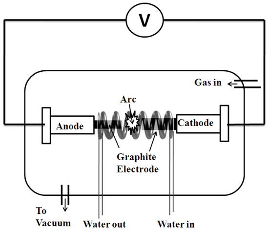
Figure 1.
Schematic diagram of dc-arc discharge set-up
If SWCNT are preferable, the anode has to be filled with metal catalyst, such as Fe, Co, Ni, Y or Mo. Experimental results show that the width and diameter distribution depends on the composition of the catalyst, the growth temperature and the various other growth conditions. If both electrodes are graphite, the main product will be MWCNTs. Typical sizes for MWCNTs are an inner diameter of 1-3nm and an outer diameter of approximately 10nm. Because no catalyst is involved in this process, there is no need for a heavy acidic purification step. This means MWCNT can be synthesized with a low amount of defects.
In most of the studies, SWCNTs are synthesized using the dc-arc discharge process by filling the catalyst powder into a hole drilled in a graphite elctrode act as an anode and arcing takes place between this anode and a pure graphite based cathode in optimized chamber conditions. In one of the study by Mathur et al. [11] SWCNTs and MWCNTs were synthesized simultaneously in a single experiment selectively. In their experiment, However, instead of filling the catalyst powder into a hole drilled in a graphite electrode; they prepared a catalyst/graphite composite electrode. Coke powder, catalyst powder, natural graphite powder and binder pitch were thoroughly mixed together in a ball mill in appropriate proportions and molded into green blocks using conventional compression molding technique. A mixture of Ni and Co powders was used as catalyst. The green blocks were heated to 1200o C in an inert atmosphere to yield carbonized blocks with varying compositions of coke, natural graphite powder, Ni and Co. These electrodes were used as the anodes in the arcing process and a high density graphite block was used as the cathode. A uniform gap of 1– 2 mm was maintained between the electrodes during the arcing process with the help of a stepper motor for a stable arc-discharge (dc voltage 20–25 V, current 100–120 A, 600 torr helium).The SWCNTs yield was found to be doubled in this case.
3.1.1. Characteristics of CNTs produced by d.c. arc discharge technique
Arc discharge is a technique that produces a mixture of components and requires separating nanotubes from the soot and the catalytic metals present in the crude product. In this technique both SWCNT and MWCNT can be produced and it has been described by several researchers.
The scanning electron microscope (SEM) and transmission electron microscope (TEM) are generally used to observe the physical appearance of any carbon based soot. Similarly, Mathur et al. [11] used SEM and TEM for the observation of SWCNT and MWCNT produced from the arc discharge technique as shown in Figure 2. In this technique, the carbon material deposits on the chamber and cathode. The arcing process resulted in the formation of web-like deposits on the inner walls of the arc chamber. A typical SEM micrograph of such deposit (Figure 2a) revealed the presence of SWNT bundles along with the amorphous carbon and catalyst particles. Rod-like microstructures aligned preferentially along the length of the cathode were also found at the tip of the cathode as shown in Figure 2b. The inset in Figure 2b shows the presence of graphitized carbon and sharp needle-like nanostructure when these rods are powdered. Upon detailed electron microscopic examination, these needles exhibited the MWCNT structure with an outer diameter of 20–25 nm (Figure 2c).
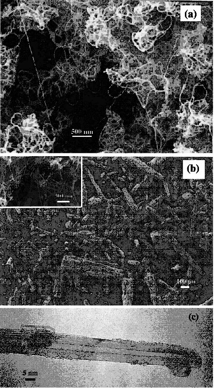
Figure 2.
(a) SEM micrograph of the chamber deposit showing the presence of long and flexible carbon nanotubes. (b) SEM micrograph of the cathode deposit showing the presence of rod-like microstructures. The inset figure shows the presence of needle-like nanostructures present within each microstructure. (c) TEM micrograph of a single needle-like nanostructure (Reprinted with permission from Elsevier (11))
The nature of the soot can be identified using Raman spectrometer and generally used for confirmation of the quality of CNTs. The nature of these two deposits obtained using this arc discharge process was confirmed from their respective Raman spectrum (Figure 3). The Raman spectrum of the chamber deposit showed the characteristic radial breathing and tangential bands at 165–183 and 1591 cm-1, respectively. The strong G-band at 1580 cm-1 in the Raman spectrum of the cathode deposit and its TEM image depicted in Figure 2c, confirmed that the cathode deposit predominantly contained MWCNTs. The prominent D-band around 1350 cm-1seen in both spectrum is attributed to the presence of disordered carbonaceous material present in the as-prepared deposits. In their study, Mathur et al. [11] show that SWCNTs deposit on the arc chamber and MWCNTs on cathode deposit.
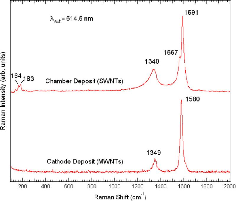
Figure 3.
Room temperature Raman spectrum of the chamber and cathode deposit (Reprinted with permission from Elsevier (11))
3.2. Chemical vapor deposition
Pyrolysis of organometallic precursors such as metallocenes (e.g. ferrocene) in a furnace provides a straight forward procedure to prepare CNT by CVD technique. Different hydrocarbons, catalyst and inert gas combinations have been used by several researchers in the past for the growth of CNT by CVD technique. In one of the study by Mathur et al. [12], CNTs were grown inside the quartz reactor by thermal decomposition of hydrocarbons, e.g. toluene in presence of iron catalyst obtained by the decomposition of organometallic like ferrocene. The furnace provided a constant temperature zone of 18 cm in the centre as shown in Figure 4. The reaction zone was maintained at 750oC. Once the temperature was reached, the solution containing a mixture of ferrocene and toluene in particular proportion (0.077 g ferrocene in 1 ml toluene) was injected in the reactor at a point where the temperature was 200oC. Argon was also fed along with the charge as a carrier gas and its flow rate was adjusted so that the maximum amount of precursor is consumed inside the desired zone.
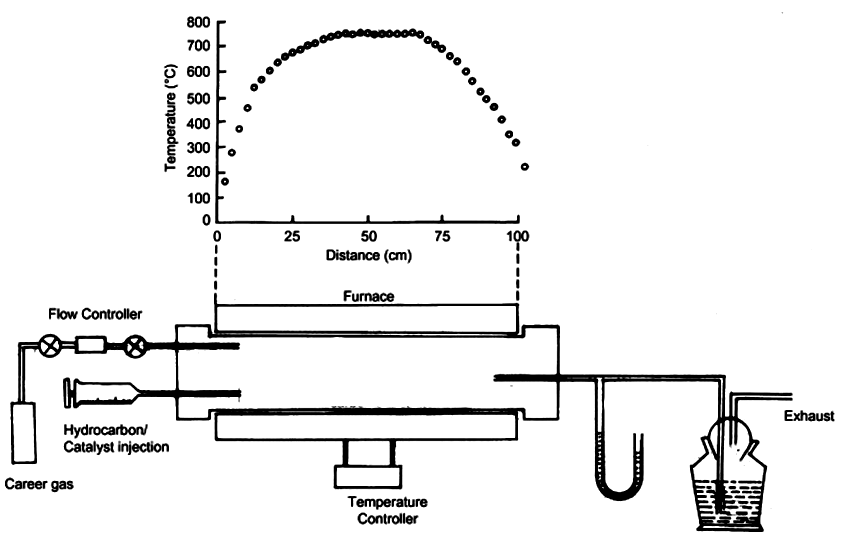
Figure 4.
Schematic diagram of the CVD reactor along with the temperature profile (Reprinted with permission from Elsevier (12))
3.2.1. Characteristics of CNTs Produced by CVD Technique
CNTs are produced in the form of big bundles using CVD technique. The physical appearance of the as produced CNTs is shown in Figure 5a and Figure 5b for SEM and TEM respectively. Figure 5a shows a big CNT bundle of length >300µm and the inset image of Figure 5a shows very good quality of uniform CNTs. Figure 5b shows the TEM image of as produced CNTs confirming the presence of MWCNT with metallic catalytic impurites either on the tip of the tube or in the cavity of of CNTs (inset of Figure 5b).
Further confirmation of the quality and type of CNTs can be obtained using Raman spectrometer as shown in Figure 6. This shows the tangential band at 1580 cm-1 (G band) of high intensity and the disorder-induced band at 1352 cm-1 (D band) as a perfect MWCNT nature [13]. The ratio of intensity of G to D band gives the information regarding the quality of the CNTs. The high value of intensity ratio of G/D band confirms the better quality of CNTs.
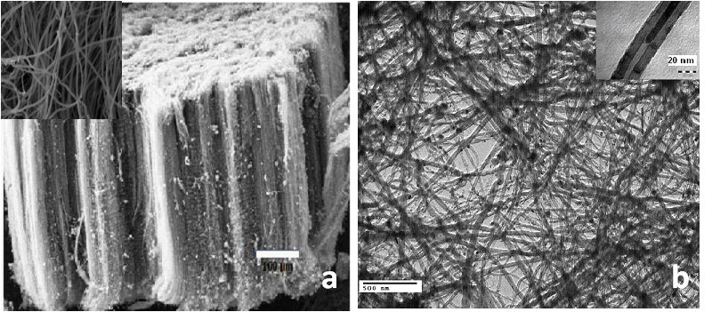
Figure 5.
(a) SEM image of aligned CNT bundle synthesized by CVD technique.The inset figure shows the very good quality of uniform CNTs (b) TEM image of as grown MWCNT and inset image shows the MWCNTs with encapsulated metallic impurities
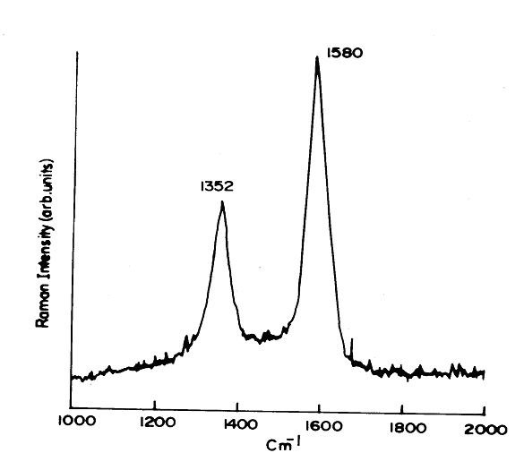
Figure 6.
Raman spectrum of CVD-grown MWCNTs.
3.3. Laser ablation
In the laser ablation process, a pulsed laser vaporizes a graphite target containing small amounts of a metal catalyst [14] as shown in Figure 7. The target is placed in a furnace at roughly 1200°C in an inert atmosphere. The nanotubes develop on the cooler surface of the reactor, as the vaporized carbon condenses. The yield of nanotube synthesis by this process is roughly 70%.
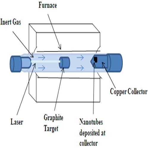
Figure 7.
Schematic diagram of Laser ablation set-up for CNT synthesis
3.3.1. Characteristics of CNTs produced by laser ablation technique
The laser-ablation prepared samples usually contain >70% nearly endless, highly tangled ropes of SWCNTs along with nanoscale impurities. The SWCNTs formed in this case are bundled together by van der Waals forces. Laser vaporisation results in a higher yield for SWCNT synthesis and a narrower size distribution than SWCNTs produced by arc-discharge [15]. The nanotubes generated by the laser ablation and arc discharge technique are relatively impure, with presence of unwanted carbonaceous impurities and not operated at higher scale; therefore, the overall production costs are high.
Compared to other methods for synthesis of CNTs, more parameters, including temperature, feeding gases, flow rate, catalyst components and heating rate are accessible to control the growth process in CVD. By changing the growth conditions, we can control the properties of the produced CNTs such as length, orientation and diameter to some extent. It has been observed that the gas phase processes produces CNTs with fewer impurities and are most amenable to large scale processing. So the gas phase techniques such as CVD, for nanotube growth offer the greatest potential for scaling up nanotube production for processing of composites.
4. Purification
During CNTs synthesis, impurities in the form of catalyst particles, amorphous carbon and non tubular fullerenes are also produced. The most of the production methods involve the use of catalysts which are normally transition metals (Fe, Co, Ni or Y), these remains in the resulting nanotubes as spherical or cylindrical particles after experiments. Through careful control of process parameters one could minimize the formation of amorphous carbon particles, so that the main impurities in CNTs are the remaining catalyst particles. However as most of these catalytic particles may either hide in internal cavity or stick firmly to the walls of CNTs, it is almost impossible to get rid of these effectively without damaging the nanotubes. Several purification methods have been tried to overcome these impurities. In one of the study by Mathur et al. [11], SWCNT soot prepared by dc arc discharge process was purified by removing various forms of impurities, such as amorphous carbon, graphitic nanoshells and catalyst particles present in the chamber deposit by applying a judicious combination of wet and dry chemical methods (acid treatment and oxidation). In this process, initially SWCNT soot were oxidized at 350 oC for 6h in air which remove the amorphous carbon followed by refluxing in HCl for the removal of metallic impurities like Ni and Co and again oxidation at 550oC for 30 min for the removal of graphitic nanoshell.The final product gives 97% purified SWCNT. The MWCNTs produced by CVD technique contains mainly ~10% metallic impruites which can be removed by heating it in the inert atmosphere at 2500oC in graphitization furnace. This process gives >99% pure MWCNTs and also helps in annealing out the defects in the tubes. This graphitization process at high temperature can also be useful for removal of impurities in the arc discharge produced SWCNTs soots with the combination of other purification steps.
5. Nanocomposites
Because of the high strength and stiffness of CNTs, they are ideal candidates for structural applications. For example, they may be used as reinforcements in high strength, low weight and high performance composites. Presently there is a great interest in exploiting the exciting properties of these CNTs by incorporating them into some form of polymer matrix.
5.1. Composite fabrication techniques
A large number of techniques have been used for the fabrication of CNT-polymer nanocomposites based on the type of polymer used.
5.1.1. Solvent casting
The solution casting is most valuable technique to form CNTs/polymer nanocomposites. However, its use is restricted to polymers that are soluble. Solvent casting facilitates nanotube dispersion and involves preparing a suspension of CNTs in the desirable polymer solution via energetic agitation (magnetic stirring or sonication) and then allowing the solvent to evaporate to produce CNT-polymer nanocomposites. A lot of study is available in open literature for the formation of CNT nanocomposites by this method [16-18]. Mathur et al. [18] cast the solutions of the MWCNT/polystyrene (PS)/toluene and MWCNT/ polymethyl methacrylate (PMMA)/toluene suspensions after sonication into a petry dish to produce nanotubes composites with enhanced electrical and mechanical properties. Benoit et al. [19] obtained electrically conductive nanocomposites by dispersing CNT and PMMA in toluene, followed by the drop casting on substrate. The choice of solvent is generally made based on the solubility of the polymer. The solvent selection for nanotube dispersion also had a significant influence on the properties of the nanocomposites and studied by Lau and co-workers [20].Their results demonstrates that, contrary to the general belief that small traces of CNTs alone will serve to strengthen the epoxy composites, the choice of the solvent used in the dispersion of CNTs also can have a significant impact. The change trend of the mechanical properties was found to be related to the boiling point of respective solvent used. In the samples observed in their study, only acetone-dispersed nanocomposites displayed improvements in flexural strength over the pure epoxy, while ethanol and DMF used in CNTs dispersion actually countered the benefits of CNTs in the resulting nanocomposites.It is reasonable that, easier the solvent can evaporate, less solvent will remain to affect the curing reaction. Their results of thermogravimetric analysis (TGA) proved the existence of residual solvent in the resulting nanocomposites. Further evidence of the solvent influence was obtained by Fourier transform infrared (FTIR) spectra, which displayed the difference in the molecular structure of the final nanocomposites depending on the solvent used. The solvent influence is attributed to the different amount of unreacted epoxide groups and the extent of cure reaction in the manufacturing process. The presence of residual solvent may alter the reaction mechanism by restricting the nucleophile–electrophile interaction between the hardener and epoxy, henceforth, affect the cross-linking density and thus degrade the transport properties [21]and mechanical properties of the cured structures. The residual solvent may absorb some heat energy from the composite systems in the pre-cured process, causing a change in local temperature. Nanocomposites with other thermoplastic materials with enhanced properties have been fabricated by solvent casting [16-18, 22]. The limitation of this method is that during slow process of solvent evaporation, nanotubes may tend to agglomerate, that leads to inhomogeneous nanotube distribution in polymer matrix. The evaporation time can be decreased by dropping the nanotube/polymer suspension on a hot substrate (drop casting) [19]or by putting suspension on a rotating substrate (spin-casting) [23]. Du et al. [24] developed a versatile coagulation method to avoid agglomeration of CNTs in PMMA-CNT nanocompositses that involves pouring a nanotube/polymer suspension into an excess of solvent. The precipitating polymer chains entrap the CNT, thereby preventing the CNT from bundling.
5.1.2. Melt mixing method
The alternative and second most commonly used method is melt mixing, which is mostly used for thermoplastics and most compatible with current industrial practices. This technique makes use of the fact that thermoplastic polymers softens when heated. Melt mixing uses elevated temperatures to make substrate less viscous and high shear forces to disrupt the nanotubes bundle. Samples of different shapes can then be fabricated by techniques such as compression molding, injection molding or extrusion. Andrews and co-workers [25] formed composites of commercial polymers such as high impact polystyrene, polypropylene and acrylonitrile–butadiene–styrene (ABS) with MWCNT by melt processing. Initially these polymers were blended in a high shear mixer with nanotubes at high loading level to form master batches that were thereafter diluted with pure polymer to form lower mass fraction samples. Compression molding was used to form composite films. A similar combination of shear mixing and compression molding is studied by many other groups discussed elsewhere [16]. Also Meincke et al. [5] mixed polyamide-6, ABS and CVD-MWCNT in a twin screw extruder at 260oC and used injection molding to make nanocomposites. Tang et al. [26] used both compression and twin-screw extrusion to form CNT/polyethylene composites. Although melt-processing technique has advantages of speed and simplicity, it is not much effective in breaking of agglomeration of CNTs and their dispersion. Bhattacharyya et al. [27] made 1 wt% CNT/polypropylene (PP) nanocomposites by melt mixing, but found that melt mixing alone did not provide uniform nanotube dispersion. Niu et el. [28] studied both methods to prepare polyvinylidene fluoride (PVDF)-CNT nanocomposites to study electrical properties and found it better in composites formed by solution casting.
5.1.3. In-situ polymerization
In addition to solvent casting and melt mixing the other method which combines nanotubes with high molecular weight polymers is in-situ polymerization starting with CNTs and monomers. In-situ polymerization has advantages over other composite fabrication methods. A stronger interface can be obtained because it is easier to get intimate interactions between the polymer and nanotube during the growth stage than afterwards [29, 30].The most common in situ polymerization methods involve epoxy in which the monomer resins and hardeners are combined with CNTs prior to polymerizing [31]. Pande and coworkers [32] performed the in-situ polymerization of MWCNT/ PMMA composites for the enhancement in flexural strength and modulus of composites. Li et al. [33] reported the fabrication and characterization of CNT/polyaniline (PANI) composites. Xiao and Zhou [34]deposited polypyrrolre (PP) and poly(3-methylthiophene) (PMet) on the surface of MWCNTs by in situ polymerization. Saini et al. [35] reported fabrication process of highly conducting polyaniline (PANI)–(MWCNT) nanocomposites by in-situ polymerization. This material was used in polystyrene for the fabrication of MWCNT-PANI-PS blend for microwave absorption [36]. Moniruzzaman [17] reported many other studies of in-situ polymerization of CNTs with different polymers. Generally, in situ polymerization can be used for the fabrication of almost any polymer composites containing CNT that can be non-covalently or covalently bound to polymer matrix. This technique enables the grafting of large polymer molecules onto the walls of CNT. This technique is particularly important for the preparation of insoluble and thermally unstable polymers, which cannot be processed by solution or melt processing.
Some studies have been also carried out using combined methods, such as solvent casting in conjunction with sonication, followed by melt mixing. Haggenmueller et al. [37] observed considerable nanotube dispersion in CNT-polymer nanocomposites using combination of solvent casting and melt mixing. Pande et al. [32, 38] also prepared MWCNT bulk composites with PMMA and PS using a two-step method of solvent casting followed by compression molding and obtained better electrical and mechanical properties. Singh et al. [39] also prepared MWCNT-LDPE composites using solvent casting followed by compression moulding and obtained better electrical conductivity. Jindal et al. [29, 40] prepared MWCNT-polycarbonate composite using solvent casting followed by compression moulding for the enhancement in the impact properties.
The other less commonly known methods for CNT- polymer nanocomposites formation are twin screw pulverization [41], latex fabrication [42], coagulation spinning [43] and electrophoretic deposition [44].
6. Challenges in MWCNT polymer composites fabrication and possible solutions
Although these fabrication methods helped to enhance the properties of CNT reinforced composites over neat polymer but there are several key challenges that hinders the excellent CNT properties to be fruitful in polymer composite formation.
6.1. Dispersion
Disperion of nanoscale filler in a matrix is the key challenge for the formation of nanocomposite. Dispersion involves separation and then stabilization of CNTs in a medium. The methods described above for the nanocomposites fabrication require CNTs to be well dispersed either in solvent or in polymer for maximizing their contact surface area with polymer matrix. As CNTs have diameters on nanoscale the entanglement during growth and the substantial van der Waals interaction between them forces to agglomerate into bundles. The ability of bundle formation of CNTs with its inert chemical structure makes these high aspect ratio fibers dissolving in common solvents to form solution quite impossible. The SEM of MWCNTs synthesized by CVD technique seems to be highly entangled and the dimensions of nanotube bundles is hundreds of micrometer. This shows several thousands of MWCNTs in one bundle as shown in Figure 5a. These bundles exhibits inferior mechanical and electrical properties as compared to individual nanotube because of slippage of nanotubes inside bundles and lower aspect ratio as compared to individual nanotube. The aggregated bundles tend to act as defect sites which adversely affect mechanical and electrical properties of nanocomposites. Effective separation requires the overcoming of the inter-tube van der Waal attraction, which is anomalously strong in CNT case. To achieve large fractions of individual CNT several methods have been employed. The most effective methods are by attaching several functional sites on the surface of CNTs through some chemical treatment or by surrounding the nanotubes with dispersing agents such as surfactant. Thereafter the difficulty of dispersion can be overcome by mechanical/physical means such as ultrasonication, high shear mixing or melt blending. Another obstacle in dispersing the CNTs is the presence of various impurities including amorphous carbon, spherical fullerenes and other metal catalyst particles. These impurities are responsible for the poor properties of CNTs reinforced composites [45].
6.2. Adhesion between CNTs and polymer
The second key challenge is in creating a good interface between nanotubes and the polymer matrix. From the research on microfiber based polymer composites over the past few decades, it is well established that the structure and properties of filler-matrix interface plays a major role in determining the structural integrity and mechanical performance of composite materials. CNTs have atomically smooth non-reactive surfaces and as such there is a lack of interfacial bonding between the CNT and the polymer chains that limits load transfer. Hence the benefits of high mechanical properties of CNTs are not utilized properly. The first experimental study focusing on interfacial interaction between MWCNT and polymer was carried out by Cooper et al. [46]. They investigated the detachment of MWCNTs from an epoxy matrix using a pullout test for individual MWCNT and observed the interfacial shear stress varied from 35-376 MPa. This variation is attributed to difference in structure and morphology of CNTs.
There are three main mechanisms for load transfer from matrix to filler. The first is weak van der Waal interaction between filler and polymer. Using small size filler and close contact at the interface can increase it. The large specific surface area of CNTs is advantageous for bonding with matrix in a composite, but is a major cause for agglomeration of CNTs. Therefore, uniformally dispersed individual nanotubes in matrix is helpful. The second mechanism of load transfer is micromechanical interlocking which is difficult in CNTs nanocomposites due to their atomically smooth surface. Although local non uniformity along length of CNTs i.e. varying diameter and bends due to non hexagonal defects contributes to this micromechanical interlocking. This interlocking can increase by using long CNTs to block the movement of polymer chains. The contribution of this mechanism may reach saturation at low CNT content. The third and best mechanism for better adhesion and hence load transfer between CNTs and polymer is covalent or ionic bonding between them. The chemical bonding between CNTs and polymer can be created and enhanced by the surface treatment such as oxidation of CNTs with acids or other chemicals. This mode of mechanism have much importance as it provides strong interaction between polymer and CNT and hence efficiently transfers the load from polymer matrix to nanotubes necessary for enhanced mechanical response in high-performance polymers.
6.3. Chemical functionalization of CNTs
The best route to achieve individual CNT to ensure better dispersion is chemical modifications of CNT surface. The chemical functionalization involves the attachment of chemical bonds to CNT surface or on end caps. Nanotube functionalization typically starts with oxidatative conditions, commonly by refluxing in nitric or sulfuric acid or combination of both to attach carboxylic acid moieties to the defect sites. The end caps of nanotubes have extra strain energy because of their high degree of curvature with pentagons and heptagonal carbon atoms are most vulnerable to reaction with acid. The side walls also containing defects like pentagon-heptagon pairs, sp3 hybridized defects and vacancies in nanotube lattice and are easily supplemented by oxidative damage and can be stabilized by formation of functional groups mainly carboxylic acid and hydroxide group. These acid moieties and hydroxide groups can be further replaced to more reactive groups like –COCl or –CORNH2. The addition of these functional groups on CNTs possesses intermolecular repulsion between functional groups on surface that overcomes the otherwise weak van der Waal attraction between CNTs. It is also vital to stabilize the dispersion to prevent reagglomeration of the CNTs. Chemical functionalization can prevent reagglomeration of CNTs also. Sen et al. [47] carried out chemical functionalization to form ester functionalized CNTs and found that it is an effective approach to exfoliate the CNTs bundles and improve their processibility with polymer matrix. Georgakilas et al. [48] observed that CNT covalently functionalized with pyrrolidone by 1,3-dipolar cycloaddition of azomethine ylides show a solubility of 50 mg/mL in chloroform, even without sonication whereas the pristine CNT is completely insoluble in this solvent. Liang et al. [49] performed reductive alkylation of CNTs using lithium and alkyl halides in liquid ammonia for sidewall functionalization of CNTs and observed their extensive debundling by inspection of HRTEM images. Kinloch et al. [50] studied the rheological behavior of oxidized CNTs and found that the composites filled with functionalized CNTs had better dispersion. It has been observed by the researchers that amine modified CNTs is very important for the enhancement in the mechanical properties with epoxy. Garg et al. [31] shows the reaction mechanism for the formation of acid functionalized and amine functionalized CNT and their interaction with the epoxy resin as Figure 8a and b respectively. Two different types of functional groups were attached on the CNT surface. In the first case MWCNTs were refluxed for 48 h in HNO3 (400 ml, 60% concentration) to achieve reasonable surface oxidation of the tubes. The mixture was then filtered and the residue (treated material) was washed several times with distilled water till washings were neutral to pH paper. The treated MWCNT were dried in oven before use. In a second step the oxidized nanotubes were dispersed in benzene by stirring, and then refluxed with excess SOCl2 along with a few drops of DMF used as catalyst for chlorination of MWCNT surfaces. After the acyl chlorination, SOCl2 and DMF were removed through repeatedly washing by tetrahydrofuran (THF). 100 ml of triethylene tetra-amine (TETA) was added to react with acyl chlorinated MWCNT at 100 °C for 24 h reflux until no HCl gas evolved. After cooling to room temperature, MWCNTs were washed with deionized water 5 times to remove excess TETA. Finally, the black solid was dried at room temperature overnight in vacuum and named as amine modified CNTs. These functionalized CNTs were characterized by FTIR, TGA and HRTEM and clearly showed the presence of these types of functional group. Gojny et al. [51]achieved surface modified MWCNTs by refluxing of oxidized MWCNTs with multifunctional amines and observed from TEM images that these were completely covered by epoxy matrix that confirmed the bonding between them. Sinnott [52]has provided an in depth review of chemical functionalization of CNTs where the chemical bonds are used to tailor the interactions between nanotubes and polymers or solvent. The chemical functionalization of CNTs has also been accomplished through irradiation with electrons or ions [53]. In this manner one may hope to improve the binding of CNTs by interdigitation of active sites on its sides into polymer matrix.
Covalent bond also benefits phonon transferring between nanotubes and polymer matrix, which is a key factor for improving thermal conductivity of the nanocomposites. To ensure the adhesion between polymer and nanotubes various surfactant and chemical modification procedures have been adopted to modify the surface of otherwise inert surface of CNTs that provides bonding sites to the polymer matrix.
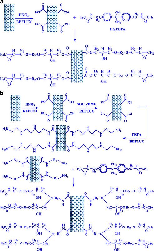
Figure 8.
Reaction mechanism for (a) acid modified-MWCNT (b) amine modified-MWCNT with epoxy resin (Reprinted with permission from Springer(31))
So the surface modification of CNTs is the crucial factor that decides the effective dispersion and improves the interactions between CNTs and matrix. However there are certain drawbacks of using chemically functionalized CNTs. Chemical functionalization normally employs harsh techniques resulting in tube fragmentation and also disrupts the bonding between graphene sheets and thereby reduces the properties of CNTs. Studies revealed that different chemical treatments may decrease the maximum buckling force of nanotubes by 15% [16]. Also the chemical functionalized CNTs significantly decrease the electrical conductivity of CNTs nanocomposites due to unbalance polarization effect, shortening of length and physical structure defects during acidic treatment [54]. But it is still necessary for increased dispersion and strengthens the interfacial bonding of CNTs with polymer matrix that is more important in structural applications.
The solubility or dispersion of CNTs in certain specified solvents or polymers can also increase by non covalent association which is more fragile. The non-ionic surfactant such as sodium dodecylbenzene sulfonate (SDS) or polyoxyethylene-8-lauryl (PoEL) has two segments. The hydrophobic segment of surfactant shows strong interactions with carbon of CNTs via van der Waal force and the hydrophilic segment shows hydrogen bonding with solvent or polymer used for dispersion. Islam et al. [55] reported that ~ 65% CNT bundles exfoliated into individual nanotubes even with a very low of 20 mg (CNT)/ml of water containing SDS as surfactant. Barrau et al. [56] used palmitic acid as surfactant to disperse CNTs into epoxy resin and observed that electrical percolation threshold decreases indicating better CNT dispersion. Gong et al. [57] added PoEL as surfactant in CNT/epoxy composite to assist the dispersion of CNTs. The improvement in dispersion in chitosan with nitric acid treated CNTs was also reported by Ozarkar et al. [58] and the stability of dispersion prepared by using functionalized CNTs was observed to be better. However, CNTs treated with different surfactants are wrapped in it and hence contacts between CNTs decreases thereby the transport properties (electrical and thermal conductivities) of CNTs/polymer nanocomposites are adversely affected.
6.4. Dispersion of high loading of CNTs in polymer matrix
Dispersion of high loading of CNTs in any polymer is very difficult due to the formation of agglomerates by the conventional techniques. To maximize the improvment in properties, higher loading of CNTs is preferred [59]. However, polymer composites synthesized by using the conventional methods generally have low CNT contents. It has been observed that beyond 1 wt.-% of loading, CNTs tend to agglomerate [60] resulting in poor mechanical properties of the composites. It is therefore important to develop a technique to incorporate higher CNT loading in the polymer matrices without sacrificing their mechanical properties. Recently, several methods have been developed for fabricating CNT/polymer composites with high CNT loadings. One such technique is mechanical densification technique where vertically aligned CNTs were densified by the capillary induced wetting with epoxy resin [61]. By this technique dimensions of sample preparation are limited. In another technique, a filtration system was used to impregnate the epoxy resin into CNT bucky paper [62, 63]. However, it was very difficult to completely impregnate the bucky paper with epoxy resin. Recently, Feng et al., [64] reported a mixed curing assisted layer by layer method to synthesize MWCNT/epoxy composite film with a high CNT loading from ~15 to ~36 wt.-%. The mixed-curing-agent consists of two types of agents, one of which is responsible for the partial initial curing at room temperature to avoid agglomeration of the CNTs, and the other for complete curing of epoxy resin at high temperature to synthesize epoxy composite films with good CNT dispersion. In another study by Feng et al. [65] upto ~39.1 wt. % SWCNT-epoxy composites were fabricated using same mixed curing layer by layer method and their mechanical properties were enhanced significantly. Bradford et al. [66] reported a method to quickly produce macroscopic CNT composites with a high volume fraction upto 27% of millimeter long, well aligned CNTs. Specifically, they used the novel method, shear pressing, to process tall, vertically aligned CNT arrays into dense aligned CNT preforms, which are subsequently processed into composites. In another study by Ogasawara et al. [67] aligned MWCNT/epoxy composites were processed using a hot-melt prepreg method. Vertically aligned ultra-long CNT arrays (forest) were converted to horizontally aligned CNT sheets by pulling them out. An aligned CNT/epoxy prepreg was fabricated using hot-melting with B-stage cured epoxy resin film. The final composites contains 21.4 vol% of MWCNTs.
6.5. Alignment of CNTs in polymer matrix
The other key challenge is to understand the effect of nanotube alignment on nanocomposites properties because the nanotubes have asymmetric structure and properties. Like other one-dimensional fiber fillers CNTs displays highest properties in the oriented reinforced direction and the mechanical, electrical, magnetic and optical performance of its composites are linked directly to their alignment in the matrix. So to take the full advantage of excellent properties of CNTs these should be aligned in a particular direction. For example, the alignment of CNT increases the elastic modulus and electrical conductivity of nanocomposites along the nanotube alignment direction.
Several methods like application of electric field during composite formation and carbon arc discharge [68], composite slicing [69], film rubbing [70], chemical vapor deposition [71, 72], mechanical stretching of CNT-polymer composites [73] and magnetic orientation [74] have been reported for aligning nanotubes in composites. Electrospinning is also an effective method for the alignment of CNTs in polymer matrix.
7. Properties of the nanocomposites
7.1. Mechanical properties of MWCNTs polymer nanocomposites
Different thermoplastic and thermoset polymer matrices have been tried to realize the superior mechanical properties of CNTs for development of light weight strong material. NASA scientists are considering CNT-polymer composite for space elevator. To date, a volume of literature is available on the improvement of mechanical performance of polymers with addition of CNTs. The first study for formation of CNT-polymer composites was carried out by Ajayan et al. [69]. CNTs were aligned within the epoxy matrix by the shear forces induced by cutting with a diamond knife, however no quantitative mechanical measurements were made. The first true study for tensile and compression properties of CNT polymer composites was carried by Schadler et al. [75] with epoxy. On addition of 5-wt% MWCNTs the tensile modulus increased from 3.1 GPa to 3.71 GPa. and compression modulus increased from 3.63 to 4.5 GPa. However, no significant increases in toughness values were observed. Bai et al. [76] observed doubling of Young’s modulus from 1.2 to 2.4 GPa and significant increase in strength from 30 to 41 MPa on addition of 1 wt.% MWCNTs. Also excellent matrix–nanotube adhesion was confirmed by the observation of nanotube breakage during fracture surface studies. Zhou et al. [77] reported steady increase of flexural modulus in CNT-epoxy composite with higher CNT weight percentage and found an improvement of 11.7% in modulus with 0.4 wt% loading of CNTs and 28% enhancement in flexural strength with 0.3 wt% loading. Garg et al. [31] reported an increment of 155 % in flexural strength of epoxy with addition of merely 0.3% amine functionalized MWCNTs and an increment of 38% in flexural modulus. Mathur et al. [13] reported an increment of 158% in flexural strength of phenolic with addition of 5 vol% of MWCNT. Colemann et al. [16] reviewed the mechanical properties of a large number of CNT reinforced polymer (thermoplastic and thermosetting) composites fabricated by various methods and reported enhancement in mechanical properties. Du et al. [78] studied the experimental results for mechanical performance of CNTs nanocomposites carried out by different research groups and observed that the gains are modest and far below the simplest theoretical estimates. Haggenmueller [79] applied the Halpen Tsai composite theory to CNT nanocomposites and observed that the experimental elastic modulus is smaller than predicted by more than one order. It is attributed to the lack of perfect load transfer from nanotubes to matrix due to non uniform dispersion and small interfacial interaction. Although chemical functionalization of CNTs has sorted out those problems to an extent yet the best results have to be achieved. Also aspect ratio is other source of uncertainty in mechanical properties. Defects on the CNT surface also expected to influence the mechanical properties significantly. The methods of handling nanotubes, including acid treatments and sonication for long time are known to shorten nanotubes results in decreasing aspect ratio and are detrimental to mechanical properties. The mechanical properties of CNT based composites increased upto a certain loading of CNTs and beyond which it starts decreasing. This may be because of increase in viscosity of polymers at higher CNTs loading and also cause some surface of CNTs not to be completely covered by polymers matrix due to the large specific surface area of CNTs.Therefore, few studies have been carried out to disperse high loading of CNTs in polymer matrices with improved mechanical properties. Bradford et al. [66] reported 400 MPa (tensile strength) and 22.3 GPa (tensile modulus) for 27vol% of MWCNT–epoxy composites. Feng et al. [80] also reported 183% and 408% improvement in tensile strength and tensile modulus respectively at 39.1 wt% SWCNTs loading compared with those of the neat epoxy. Ogasawara et al. [67] found 50.6 GPa and 183 MPa modulus and ultimate tensile strength respectively of CNT (21.4 vol.%)/epoxy composite. These values were 19 and 2.9 times those of the epoxy resin respectively.
Andrews et al. [80] prepared aligned CNT/pitch composites and found the significant improvement in the electrical and mechanical properties especially due to orientation of CNTs. Du et al. [78] compared the mechanical performance of randomly oriented and aligned CNTs polymer composites. Their study revealed that in aligned CNT polymer nanocomposites tensile strength and modulus even reached to 3600 MPa and 80 GPA respectively which is much higher than the general value of 100 MPa and 6 GPa in case of randomly oriented CNT polymer nanocomposites. They also observed that the mechanical properties are always higher for aligned CNTs composites with higher loading while the case is different for isotropic CNT polymer composites.
7.2. Electrical properties of MWCNTs polymer nanocomposites
CNTs because of their extraordinary electrical conductivity are also excellent additive to impart electrical conductivity to polymer. Many experimental results shows that the conductive CNT composites can be constructed at low loading of CNTs due to low percolation threshold originated from the high aspect ratio and conductivity of CNTs [70, 78]. Figure 9 shows the general trend of electrical conductivity of CNT- polymer nanocomposites. It can be found from almost all the experimental results and also obvious from figure that CNT nanocomposites exhibit a typical percolation behavior and CNT reinforcement to polymers can increase the conductivity of resulting composites to several order of magnitude or even some times higher than ten orders of magnitude.
According to percolation theory the conductivity follow the following power law close to threshold percolation.
where
Sandler et al. [82] observed the percolation threshold of CNTs/epoxy nanocomposites between 0.0225 and 0.04 wt %. They further observed very low percolation threshold at 0.0025 wt% for aligned CNT- epoxy composites [83]. The current voltage behavior measurements exhibited non-ohmic behavior, which is most likely due to tunneling conduction mechanism. The main mechanism of conduction between adjacent nanotubes is probably electron hopping when their separation distance is small. At concentration greater than percolation threshold, conducting paths are formed through the whole nanocomposites, because the distance between the conductive CNT filler (individual or bundles) is small enough to allow efficient electron hopping.
The electrical conductivity of CNT/polymer composites also effected by dispersion and aspect ratio of CNTs and was studied by Barrau et al. [56]. They used palmitic acid as surfactant to improve the nanotube dispersion and reduced the threshold concentration from 0.18 to 0.08 wt%. To study the effect of aspect ratio on electrical conductivity of CNT nanocomposites Bai et al. [84] pretreated MWCNTs to alter their aspect ratios before preparing epoxy/MWCNTs composites and found that the threshold concentration varied from 0.5 to > 4 wt % with decreasing aspect ratio. The effect of alignment of CNTs in polymer composites was also studied. Du et al. [24] found some contradictory results with respect to alignment of rod like fillers and observed the lowest percolation threshold and maximum conductivity with their random orientation. They found that the electrical conductivity of 2 wt% CNT/PMMA nanocomposites decrease significantly (from ~10-4 to ~10-10 S/cm) when CNTs were highly aligned. In contrast Choi et al. [85] observed that the nanotube alignment increased the conductivity of a 3 wt% CNT/epoxy composites from ~10-7 to ~10-6S/cm. In most of the cases the CNT nanocomposites with isotropic nanotubes orientation have greater electrical conductivity than the nanocomposites with highly aligned CNTs especially at lower CNT loadings. By alignment of CNTs in polymers, the percolation pathway is destroyed as aligned CNTs seldomly intersects each other. At higher CNTs loading the conductivity is more in case of aligned CNTs as compared to randomly oriented CNTs.
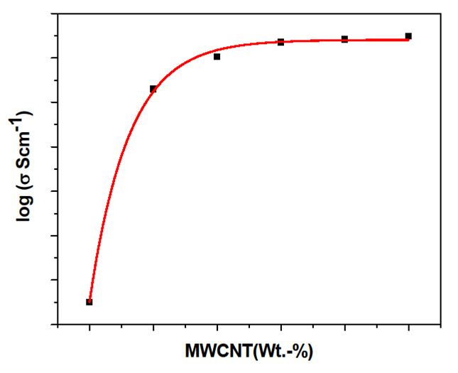
Figure 9.
General trend of electrical conductivity of CNT polymer composites
The study carried out by different researchers also revealed that the composites with thermoplastic polymers have higher conductivity as compared to that of thermosetting polymers above percolation threshold. Transport properties in CNT-PMMA composites have been reported by Stephan et al. [86] and Benoit et al. [19] where low percolation threshold of 0.5 wt% and 0.33 wt% respectively were obtained. Singhai et al. [87] found that increase in number of defects lead to a decrease in conductivity. However Lau et al. [88] concluded that fuctionalization of CNTs can enhance the electrical conductivity of MWCNTs. The reason attributed to this phenomenon is electron transfer from the carbon atoms on MWCNTs to functionalized groups attached to the surface favorably promoting conductivity. The study carried out by Grimes et al. [89] revealed that the electrical response of as fabricated MWCNTs is significantly influenced by the presence of residual catalyst metal particles.
7.3. EMI shielding proerties of MWCNTs polymer nanocomposites
The electrical conductivity of CNT reinforced polymer composites makes them a very suitable candidate to be employed for electromagnetic interference (EMI) shielding. EMI is the process by which disruptive electromagnetic energy is transmitted from one electronic device to another via radiation or conduction. As we all know that the electromagnetic waves produced from some electronic instrument have an adverse effect on the performance of the other equipments present nearby causing data loss, introduction of noise, degradation of picture quality etc. The common example is the appearance of noise in television signal when a telephone or mobile rings. Also recent reports of deterious effects of electromagnetic radiations on electro medical devices have caused concern among health care providers. The overlapping of signals transmitted in air traffic system with signals from other electronic equipments became cause of several accidents in past. Also mobile phones and passing taxi radios have been known to interfere with anti-skid braking system (ABS), airbags and other electronic equipments causing drivers to lose control. In today’s scenario where rapid communication is required, there is an increase in electromagnetic radiations within the spectrum in which the wireless, cordless and satellite system operates. So it a strong desire to shield electronics equipments from the undesired signals. Problems with EMI can be minimized or sometime eliminated by ensuring that all electronic equipments are operated with a good housing to keep away unwanted radio frequency from entering or leaving. The shielding effectiveness (SE) of the shielding material is its ability to attenuate the propagation of electromagnetic waves through it and measured in decibels (dB) given by
where
One of the important criterion for a material to be used for EMI shielding material is that it should be electrically conducting. Because of their high electrical conductivity metals have been used for past several years as EMI shielding materials. But the shortcomings of metals like heavy weight, physical rigidity and corrosion restricts their use. The most notable substance that could overcome these shortcomings is the CNT-polymer composites. As discussed in previous sections these are electrically conductive, having low density, corrosion resistant and can be molded in any form. Due to easy processing and good flexibility, CNT–polymer composites have been employed for application as promising EMI shielding materials. The SE of the CNT-polymer composites depends on various factors like,type of CNTs (either SWCNT or MWCNT), aspect ratio of CNTs, quality of CNTs, thickness and electrical conductivity of the shielding material. Several studies have been reported on EMI shielding properties of randomly oriented CNT based polymer composites. Mathur and co-workers [18] have prepared MWNT-PMMA and MWNT-PS composites and observed 18dB and 17dB SE respectively with 10-wt % MWCNT loading. Singh et al. [90] reported a SE of 51 dB by using MWCNT grown carbon fibre fabric based epoxy composites with improved mechanical properties [91].The effect of the length (aspect ratio) of CNTs on EMI SE of composites was also studied by few researchers. Huang et al. [92] reported EMI SE of 18 dB with 15 wt.-% small CNTs and 23-28 dB with 15 wt% long CNTs in X band (8-12.4 GHz). Li et al. [93] also observed that SE with long length CNTs is more as compared to small length CNTs at the same 15wt % loading composites. The residual catalyst metal particle in the cavity of CNTs also effects the SE of the composites.
There are few additional advantages of using MWCNTs as EMI shielding material. The EMI SE also depends on the source of origin of electromagnetic waves. Electrically conducting material can effectively shield the electromagnetic waves generated from an electric source, whereas magnetic materials effectively shield the electromagnetic waves generated from a magnetic source. The MWCNTs exhibits electrical properties because of presence of pi electrons and magnetic properties because of the presence of catalytic iron particles in tubes. Also one common problem experienced with commonly used composite materials for EMI shielding is build up of heat in the substance being shielded. The possible solution for this is to add thermal conducting material. Composites with MWCNTs can easily overcome this problem as it has high thermal conductivity.
7.4. Thermal properties of MWCNTs polymer nanocomposites
As discussed above that the CNTs have thermal conductivity as high as 6600W/mK predicted for SWCNTs [94] at room temperature and have experimental value 3000W/mK for isolated MWCNT. So it is quite expected that the reinforcement of CNTs can significantly enhance the thermal properties of CNT-polymer nanocomposites. The improvement in thermal transport properties of CNT polymer composites leads their applications for usage as printed circuit boards, connectors, thermal interface materials, heat sinks.
8. Conclusion
Synthesis of high quality and reproducible CNTs is still remain a very importnat issue. Chemical vapor deposition has been found an efficient process for the synthseis of bulk quantity of CNTs. The CNT-polymer composites have been developed with improved mechanical properties but for actual structural applications, these have to compete with the existing carbon fibre based composites. Dispersion of high loading of CNTs and their alignment in any polymer matrix without sacrificing their mechanical properties is still a challenge for using CNTs in high performance composites for specific applications such as as automobile, defence, aerospace, sports etc. CNT- carbon fibres-polymer multiscale composites could be an alternative route for further improvement in the mechanical properties of the composites over commercially available CF-polymer composites. Till then electrical properties of CNT polymer composites provides exciting possibility as antistatic and electromagnetic interference shielding material.
References
- 1.
Ajayan PM, Zhou OZ. Applications of carbon nanotubes. Carbon Nanotubes2001. p. 391-425. - 2.
Lourie O, Wagner HD. Evaluation of Young's modulus of carbon nanotubes by micro-Raman spectroscopy. Journal of Materials Research 1998;13:2418-22. - 3.
Yu MF, Files BS, Arepalli S, Ruoff RS. Tensile loading of ropes of single wall carbon nanotubes and their mechanical properties. Phys Rev Lett 2000;84:5552-5. - 4.
Yu MF, Lourie O, Dyer MJ, Moloni K, Kelly TF, Ruoff RS. Strength and breaking mechanism of multiwalled carbon nanotubes under tensile load. Science 2000;287:637-40. - 5.
Meincke O, Kaempfer D, Weickmann H, Friedrich C, Vathauer M, Warth H. Mechanical properties and electrical conductivity of carbon-nanotube filled polyamide-6 and its blends with acrylonitrile/butadiene/styrene. Polymer 2004;45:739-48. - 6.
Ebbesen TW, Lezec HJ, Hiura H, Bennett JW, Ghaemi HF, Thio T. Electrical conductivity of individual carbon nanotubes. Nature 1996;382:54-6. - 7.
Lee JO, Park C, Kim JJ, Kim J, Park JW, Yoo KH. Formation of low-resistance ohmic contacts between carbon nanotube and metal electrodes by a rapid thermal annealing method. Journal of Physics D-Applied Physics 2000;33:1953-6. - 8.
Hone J. Dekker Encyclopedia of Nanoscience and Nanotechnology 2004. - 9.
Jung SH, Kim MR, Jeong SH, Kim SU, Lee OJ, Lee KH, et al. High-yield synthesis of multi-walled carbon nanotubes by arc discharge in liquid nitrogen. Applied Physics a-Materials Science & Processing 2003;76:285-6. - 10.
Ebbesen TW, Ajayan PM. LARGE-SCALE SYNTHESIS OF CARBON NANOTUBES. Nature 1992;358:220-2. - 11.
Mathur RB, Seth S, Lal C, Rao R, Singh BP, Dhami TL, et al. Co-synthesis, purification and characterization of single- and multi-walled carbon nanotubes using the electric arc method. Carbon 2007;45:132-40. - 12.
Mathur RB, Chatterjee S, Singh BP. Growth of carbon nanotubes on carbon fibre substrates to produce hybrid/phenolic composites with improved mechanical properties. Composites Science and Technology 2008;68:1608-15. - 13.
Mathur RB, Singh BP, Dhami TL, Kalra Y, Lal N, Rao R, et al. Influence of Carbon Nanotube Dispersion on the Mechanical Properties of Phenolic Resin Composites. Polymer Composites 31:321-7. - 14.
Guo T, Nikolaev P, Thess A, Colbert DT, Smalley RE. CATALYTIC GROWTH OF SINGLE-WALLED NANOTUBES BY LASER VAPORIZATION. Chem Phys Lett 1995;243:49-54. - 15.
Thess A, Lee R, Nikolaev P, Dai HJ, Petit P, Robert J, et al. Crystalline ropes of metallic carbon nanotubes. Science 1996;273:483-7. - 16.
Coleman JN, Khan U, Blau WJ, Gun'ko YK. Small but strong: A review of the mechanical properties of carbon nanotube-polymer composites. Carbon 2006;44:1624-52. - 17.
Moniruzzaman M, Winey KI. Polymer nanocomposites containing carbon nanotubes. Macromolecules 2006;39:5194-205. - 18.
Mathur RB, Pande S, Singh BP, Dhami TL. Electrical and mechanical properties of multi-walled carbon nanotubes reinforced PMMA and PS composites. Polymer Composites 2008;29:717-27. - 19.
Benoit JM, Corraze B, Lefrant S, Blau WJ, Bernier P, Chauvet O. Transport properties of PMMA-carbon nanotubes composites. Synth Met 2001;121:1215-6. - 20.
Lau KT, Lu M, Lam CK, Cheung HY, Sheng FL, Li HL. Thermal and mechanical properties of single-walled carbon nanotube bundle-reinforced epoxy nanocomposites: the role of solvent for nanotube dispersion. Composites Science and Technology 2005;65:719-25. - 21.
Bryning MB, Milkie DE, Islam MF, Kikkawa JM, Yodh AG. Thermal conductivity and interfacial resistance in single-wall carbon nanotube epoxy composites. Applied Physics Letters 2005;87. - 22.
Singh BP, Singh D, Mathur RB, Dhami TL. Influence of Surface Modified MWCNTs on the Mechanical, Electrical and Thermal Properties of Polyimide Nanocomposites. Nanoscale Research Letters 2008;3:444-53. - 23.
de la Chapelle ML, Stephan C, Nguyen TP, Lefrant S, Journet C, Bernier P, et al. Raman characterization of singlewalled carbon nanotubes and PMMA-nanotubes composites. Synth Met 1999;103:2510-2. - 24.
Du FM, Fischer JE, Winey KI. Coagulation method for preparing single-walled carbon nanotube/poly(methyl methacrylate) composites and their modulus, electrical conductivity, and thermal stability. Journal of Polymer Science Part B-Polymer Physics 2003;41:3333-8. - 25.
Andrews R, Jacques D, Qian DL, Rantell T. Multiwall carbon nanotubes: Synthesis and application. Accounts of Chemical Research 2002;35:1008-17. - 26.
Tang WZ, Santare MH, Advani SG. Melt processing and mechanical property characterization of multi-walled carbon nanotube/high density polyethylene (MWNT/HDPE) composite films. Carbon 2003;41:2779-85. - 27.
Bhattacharyya AR, Sreekumar TV, Liu T, Kumar S, Ericson LM, Hauge RH, et al. Crystallization and orientation studies in polypropylene/single wall carbon nanotube composite. Polymer 2003;44:2373-7. - 28.
Niu C, Ngaw L, Fischer A, Hoch R, Fischer AB, Ngam L. Piezoelectric high damping material for vibration suppression in vehicle, has carbon nano tube as piezoelectric electroconductive particle for packing. Hyperion Catalysis Int Inc. - 29.
Jia ZJ, Wang ZY, Xu CL, Liang J, Wei BQ, Wu DH, et al. Study on poly(methyl methacrylate)/carbon nanotube composites. Materials Science and Engineering a-Structural Materials Properties Microstructure and Processing 1999;271:395-400. - 30.
Velasco-Santos C, Martinez-Hernandez AL, Fisher FT, Ruoff R, Castano VM. Improvement of thermal and mechanical properties of carbon nanotube composites through chemical functionalization. Chemistry of Materials 2003;15:4470-5. - 31.
Garg P, Singh BP, Kumar G, Gupta T, Pandey I, Seth RK, et al. Effect of dispersion conditions on the mechanical properties of multi-walled carbon nanotubes based epoxy resin composites. Journal of Polymer Research 2011;18:1397-407. - 32.
Pande S, Mathur RB, Singh BP, Dhami TL. Synthesis and Characterization of Multiwalled Carbon Nanotubes-Polymethyl Methacrylate Composites Prepared by In Situ Polymerization Method. Polymer Composites 2009;30:1312-7. - 33.
Li XH, Wu B, Huang JE, Zhang J, Liu ZF, Li HI. Fabrication and characterization of well-dispersed single-walled carbon nanotube/polyaniline composites. Carbon 2003;41:1670-3. - 34.
Xiao QF, Zhou X. The study of multiwalled carbon nanotube deposited with conducting polymer for supercapacitor. Electrochimica Acta 2003;48:575-80. - 35.
Saini P, Choudhary V, Singh BP, Mathur RB, Dhawan SK. Polyaniline-MWCNT nanocomposites for microwave absorption and EMI shielding. Materials Chemistry and Physics 2009;113:919-26. - 36.
Saini P, Choudhary V, Singh BP, Mathur RB, Dhawan SK. Enhanced microwave absorption behavior of polyaniline-CNT/polystyrene blend in 12.4-18.0 GHz range. Synth Met;161:1522-6. - 37.
Haggenmueller R, Gommans HH, Rinzler AG, Fischer JE, Winey KI. Aligned single-wall carbon nanotubes in composites by melt processing methods. Chem Phys Lett 2000;330:219-25. - 38.
Pande S, Singh BP, Mathur RB, Dhami TL, Saini P, Dhawan SK. Improved Electromagnetic Interference Shielding Properties of MWCNT-PMMA Composites Using Layered Structures. Nanoscale Research Letters 2009;4:327-34. - 39.
Singh BP, Prabha, Saini P, Gupta T, Garg P, Kumar G, et al. Designing of multiwalled carbon nanotubes reinforced low density polyethylene nanocomposites for suppression of electromagnetic radiation. J Nanopart Res 2011;13:7065-74. - 40.
Jindal P, Pande S, Sharma P, Mangla V, Chaudhury A, Patel D, et al. High strain rate behavior of multi-walled carbon nanotubes–polycarbonate composites. Composites Part B: Engineering. - 41.
Xia HS, Wang Q, Li KS, Hu GH. Preparation of polypropylene/carbon nanotube composite powder with a solid-state mechanochemical pulverization process. Journal of Applied Polymer Science 2004;93:378-86. - 42.
Regev O, ElKati PNB, Loos J, Koning CE. Preparation of conductive nanotube-polymer composites using latex technology. Advanced Materials 2004;16:248-+. - 43.
Vigolo B, Penicaud A, Coulon C, Sauder C, Pailler R, Journet C, et al. Macroscopic fibers and ribbons of oriented carbon nanotubes. Science 2000;290:1331-4. - 44.
Dhand C, Arya SK, Singh SP, Singh BP, Datta M, Malhotra BD. Preparation of polyaniline/multiwalled carbon nanotube composite by novel electrophoretic route. Carbon 2008;46:1727-35. - 45.
Montoro LA, Rosolen JM. A multi-step treatment to effective purification of single-walled carbon nanotubes. Carbon 2006;44:3293-301. - 46.
Cooper CA, Cohen SR, Barber AH, Wagner HD. Detachment of nanotubes from a polymer matrix. Applied Physics Letters 2002;81:3873-5. - 47.
Sen R, Zhao B, Perea D, Itkis ME, Hu H, Love J, et al. Preparation of single-walled carbon nanotube reinforced polystyrene and polyurethane nanofibers and membranes by electrospinning. Nano Letters 2004;4:459-64. - 48.
Georgakilas V, Kordatos K, Prato M, Guldi DM, Holzinger M, Hirsch A. Organic functionalization of carbon nanotubes. Journal of the American Chemical Society 2002;124:760-1. - 49.
Liang F, Sadana AK, Peera A, Chattopadhyay J, Gu ZN, Hauge RH, et al. A convenient route to functionalized carbon nanotubes. Nano Letters 2004;4:1257-60. - 50.
Kinloch IA, Roberts SA, Windle AH. A rheological study of concentrated aqueous nanotube dispersions. Polymer 2002;43:7483-91. - 51.
Gojny FH, Nastalczyk J, Roslaniec Z, Schulte K. Surface modified multi-walled carbon nanotubes in CNT/epoxy-composites. Chem Phys Lett 2003;370:820-4. - 52.
Sinnott SB. Chemical functionalization of carbon nanotubes. Journal of Nanoscience and Nanotechnology 2002;2:113-23. - 53.
Crespi VH, Chopra NG, Cohen ML, Zettl A, Radmilovic V. Site-selective radiation damage of collapsed carbon nanotubes. Applied Physics Letters 1998;73:2435-7. - 54.
Sulong AB. MN, Sahari J., Ramli R., Deros BM., Park J. Electrical Conductivity Behaviour of Chemical Functionalized MWCNTs Epoxy Nanocomposites. European Journal of Scientific Research 2009;29:13-21. - 55.
Islam MF, Rojas E, Bergey DM, Johnson AT, Yodh AG. High weight fraction surfactant solubilization of single-wall carbon nanotubes in water. Nano Letters 2003;3:269-73. - 56.
Barrau S, Demont P, Perez E, Peigney A, Laurent C, Lacabanne C. Effect of palmitic acid on the electrical conductivity of carbon nanotubes-epoxy resin composites. Macromolecules 2003;36:9678-80. - 57.
Gong XY, Liu J, Baskaran S, Voise RD, Young JS. Surfactant-assisted processing of carbon nanotube/polymer composites. Chemistry of Materials 2000;12:1049-52. - 58.
Ozarkar S, Jassal M, Agrawal AK. Improved dispersion of carbon nanotubes in chitosan. Fibers and Polymers 2008;9:410-5. - 59.
Park JG, Louis J, Cheng QF, Bao JW, Smithyman J, Liang R, et al. Electromagnetic interference shielding properties of carbon nanotube buckypaper composites. Nanotechnology 2009;20. - 60.
Yang K, Gu MY, Guo YP, Pan XF, Mu GH. Effects of carbon nanotube functionalization on the mechanical and thermal properties of epoxy composites. Carbon 2009;47:1723-37. - 61.
Wardle BL, Saito DS, Garcia EJ, Hart AJ, de Villoria RG, Verploegen EA. Fabrication and characterization of ultrahigh-volume-fraction aligned carbon nanotube-polymer composites. Advanced Materials 2008;20:2707-+. - 62.
Gou JH. Single-walled nanotube bucky paper and nanocomposite. Polymer International 2006;55:1283-8. - 63.
Wang Z, Liang ZY, Wang B, Zhang C, Kramer L. Processing and property investigation of single-walled carbon nanotube (SWNT) buckypaper/epoxy resin matrix nanocomposites. Composites Part a-Applied Science and Manufacturing 2004;35:1225-32. - 64.
Feng QP, Yang JP, Fu SY, Mai YW. Synthesis of carbon nanotube/epoxy composite films with a high nanotube loading by a mixed-curing-agent assisted layer-by-layer method and their electrical conductivity. Carbon 2010;48:2057-62. - 65.
Feng QP, Shen XJ, Yang JP, Fu SY, Mai YW, Friedrich K. Synthesis of epoxy composites with high carbon nanotube loading and effects of tubular and wavy morphology on composite strength and modulus. Polymer 2011;52:6037-45. - 66.
Bradford PD, Wang X, Zhao HB, Maria JP, Jia QX, Zhu YT. A novel approach to fabricate high volume fraction nanocomposites with long aligned carbon nanotubes. Composites Science and Technology 2010;70:1980-5. - 67.
Ogasawara T, Moon SY, Inoue Y, Shimamura Y. Mechanical properties of aligned multi-walled carbon nanotube/epoxy composites processed using a hot-melt prepreg method. Composites Science and Technology 2011;71:1826-33. - 68.
Wang XK, Lin XW, Dravid VP, Ketterson JB, Chang RPH. GROWTH AND CHARACTERIZATION OF BUCKYBUNDLES. Applied Physics Letters 1993;62:1881-3. - 69.
Ajayan PM, Stephan O, Colliex C, Trauth D. ALIGNED CARBON NANOTUBE ARRAYS FORMED BY CUTTING A POLYMER RESIN-NANOTUBE COMPOSITE. Science 1994;265:1212-4. - 70.
Deheer WA, Bacsa WS, Chatelain A, Gerfin T, Humphreybaker R, Forro L, et al. ALIGNED CARBON NANOTUBE FILMS - PRODUCTION AND OPTICAL AND ELECTRONIC-PROPERTIES. Science 1995;268:845-7. - 71.
Fan SS, Chapline MG, Franklin NR, Tombler TW, Cassell AM, Dai HJ. Self-oriented regular arrays of carbon nanotubes and their field emission properties. Science 1999;283:512-4. - 72.
Li WZ, Xie SS, Qian LX, Chang BH, Zou BS, Zhou WY, et al. Large-scale synthesis of aligned carbon nanotubes. Science 1996;274:1701-3. - 73.
Jin L, Bower C, Zhou O. Alignment of carbon nanotubes in a polymer matrix by mechanical stretching. Applied Physics Letters 1998;73:1197-9. - 74.
Smith BW, Benes Z, Luzzi DE, Fischer JE, Walters DA, Casavant MJ, et al. Structural anisotropy of magnetically aligned single wall carbon nanotube films. Applied Physics Letters 2000;77:663-5. - 75.
Schadler LS, Giannaris SC, Ajayan PM. Load transfer in carbon nanotube epoxy composites. Applied Physics Letters 1998;73:3842-4. - 76.
Bai J. Evidence of the reinforcement role of chemical vapour deposition multi-walled carbon nanotubes in a polymer matrix. Carbon 2003;41:1325-8. - 77.
Zhou YX, Pervin F, Lewis L, Jeelani S. Experimental study on the thermal and mechanical properties of multi-walled carbon nanotube-reinforced epoxy. Materials Science and Engineering a-Structural Materials Properties Microstructure and Processing 2007;452:657-64. - 78.
Du JH, Bai J, Cheng HM. The present status and key problems of carbon nanotube based polymer composites. Express Polymer Letters 2007;1:253-73. - 79.
Haggenmueller R, Zhou W, Fischer JE, Winey KI. Production and characterization of polymer nanocomposites with highly aligned single-walled carbon nanotubes. Journal of Nanoscience and Nanotechnology 2003;3:105-10. - 80.
Andrews R, Jacques D, Rao AM, Rantell T, Derbyshire F, Chen Y, et al. Nanotube composite carbon fibers. Applied Physics Letters 1999;75:1329-31. - 81.
D. Stauffer AA. Introduction to percolation theory. Taylor & Francis; 1992. - 82.
Sandler J, Shaffer MSP, Prasse T, Bauhofer W, Schulte K, Windle AH. Development of a dispersion process for carbon nanotubes in an epoxy matrix and the resulting electrical properties. Polymer 1999;40:5967-71. - 83.
Sandler JKW, Kirk JE, Kinloch IA, Shaffer MSP, Windle AH. Ultra-low electrical percolation threshold in carbon-nanotube-epoxy composites. Polymer 2003;44:5893-9. - 84.
Bai JB, Allaoui A. Effect of the length and the aggregate size of MWNTs on the improvement efficiency of the mechanical and electrical properties of nanocomposites - experimental investigation. Composites Part a-Applied Science and Manufacturing 2003;34:689-94. - 85.
Choi ES, Brooks JS, Eaton DL, Al-Haik MS, Hussaini MY, Garmestani H, et al. Enhancement of thermal and electrical properties of carbon nanotube polymer composites by magnetic field processing. Journal of Applied Physics 2003;94:6034-9. - 86.
Stephan C, Nguyen TP, Lahr B, Blau W, Lefrant S, Chauvet O. Raman spectroscopy and conductivity measurements on polymer-multiwalled carbon nanotubes composites. Journal of Materials Research 2002;17:396-400. - 87.
Singjai P, Changsarn S, Thongtem S. Electrical resistivity of bulk multi-walled carbon nanotubes synthesized by an infusion chemical vapor deposition method. Materials Science and Engineering: A 2007;443:42-6. - 88.
Lau CH, Cervini R, Clarke SR, Markovic MG, Matisons JG, Hawkins SC, et al. The effect of functionalization on structure and electrical conductivity of multi-walled carbon nanotubes. J Nanopart Res 2008;10:77-88. - 89.
Grimes CA, Dickey EC, Mungle C, Ong KG, Qian D. Effect of purification of the electrical conductivity and complex permittivity of multiwall carbon nanotubes. Journal of Applied Physics 2001;90:4134-7. - 90.
Singh BP, Choudhary V, Saini P, Mathur RB. Designing of epoxy composites reinforced with carbon nanotubes grown carbon fiber fabric for improved electromagnetic interference shielding. AIP Adv 2012;2:6. - 91.
Mathur RB, Singh, B.P,Tiwari, P.K., Gupta, T.K.Choudhary, V. Enhancement in the thermomechanical properties of carbon fibre-carbon nanotubes-epoxy hybrid composites. International Journal of Nanotechnology 2012;9:1040-1049. - 92.
Huang Y, Li N, Ma Y, Feng D, Li F, He X, et al. The influence of single-walled carbon nanotube structure on the electromagnetic interference shielding efficiency of its epoxy composites. Carbon 2007;45:1614-21. - 93.
Li N, Huang Y, Du F, He XB, Lin X, Gao HJ, et al. Electromagnetic interference (EMI) shielding of single-walled carbon nanotube epoxy composites. Nano Letters 2006;6:1141-5. - 94.
Berber S, Kwon YK, Tomanek D. Unusually high thermal conductivity of carbon nanotubes. Phys Rev Lett 2000;84:4613-6.