
Abstract
Many building systems are known to have complex structure with large dimension variables that characterize its mathematical models. In such case, it is basically desirable to use avoid the use of centralized controller due to the possibility of dimension increase during its implementation. The design of decentralized controller has faced tremendous success especially for large scale systems. The main objective of this book chapter is to design decentralized controller for building system in order to avoid the damages that will be caused by the earth quake responses. This controller is designed to increase the robustness and improve the smart building system responses toward different earth quakes. The optimized behavior of the control system has been analyzed and tested in the framework of the inclusion-contraction of the overlapping decomposition theories. Moreover, the application of this control strategy to smart building system has led to significantly minimize the damages that can be generally caused by the severe earth quakes. Thence, the obtained results have demonstrated the usefulness of the proposed controller for constructing smart cities.
Keywords
- decentralized controller
- earth quake responses
- overlapping decomposition
- smart building systems
- smart cities
1. Introduction
Describing the behavior of many mechanical and engineering systems may let us end up with high dimensional mathematical models. The analysis and design problems of such systems become very complex; since the solution may not be found easily due to the huge amount of computation efforts required to simulate and analyze the dynamic process of the system, which may lead to large scale decentralized controller [1]. Therefore, new techniques and strategies should be designed in order to optimize the controller through decomposing it into simpler subsystems, so that, the control of such systems can be combined together in order to control the original global system. The objective of this paper is to design a decentralized optimal controller of well-known example of overlapping system using extension principle; our work is development of (
2. System description
Construction engineering is very important term that gathers many disciplines that varies from physics, mechanics, electronics and control [1]. It is applied science, for which engineers build different structures within the scope of civil engineering, smart building systems; thus, it is scientific discipline to the design of building that defines smart cities [2]. People combined a practical knowledge of materials and construction with the mathematics and science that were then available [3].
Consider the mechanical second order building system shown in Figures 1 and 2. The system is composed of six floor build in concrete cement and it is under continuous vibrations created by the continuous movement of the earth and earthquakes. The system’s dynamic is described by first order differential equation written in the matrix form, the size of the matrix is proportional to the number of floors and earthquake sensors installed for each as well as the actuators at the level of each floor or set of floors. The actuators are designed to create a counter force synchronously to the building dynamic.
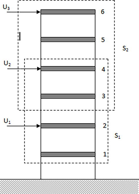
Figure 1.
Overlapping structure of building system [
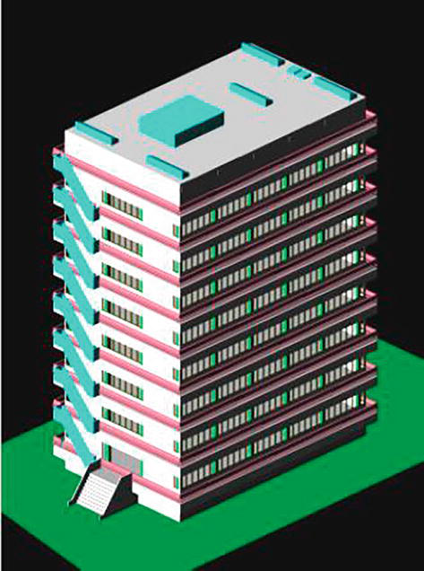
Figure 2.
Overlapping structure of real building system [
The system shown in Figure 1 can be represented by the following mathematical model
Where:
Eq. (1) indicate the response of building system to earthquake; Figure 3 shows a failure response to real earthquake system [1, 4].

Figure 3.
Failure response of a building system to earthquake disturbances [
Eq. (1) can be written as.
or
Where
And
Where dashed lines indicate the subsystems, in this example we have only two subsystems
3. Expansion and contraction
We have the overlapping system (1) and we want to transform it into non-overlapping system described by
To do that we consider the transformation matrices between systems (1) and (3)
The system described by Eq. (3) is said to be an expansion of the system described by (1) (or the system described by (1) is considered to be a contraction of the system (3)) if there exist transformation
Essentially there exist two (02) methods to derive condition of extension:
Method one
Requires working directly with the matrix second order equation in both original and extended system which means we need to use the matrices
Method two
Starts by transforming the second order system into an equivalent first order system
Consider the system (1) and its expansion (3); define the state vectors
Where
And
Consider the transformation
This implies that
Theorem one
The system
These equations are found by transforming the system (1) and (3) into state space model [6].
Eq. (10) can be written as
With
Where
Theorem two
The system (2) is an expansion of the system (1) if
Eq. (12) is satisfied by choosing the complementary matrices as
4. Contractibility of controllers
Let us consider the controller given by Eq. (14), for the overlapping building system
And Let us consider the controller given by Eq. (15) for the expanded system of the building system:
Where
Theorem three
The controller described by Eq. (15) is contractible to the controller given by Eq. (14) if and only if
Theorem four
If Eq. (2) is an extension of Eq. (1) and if Eq. (2) is stable (respectively asymptotically stable) then Eq. (1) is stable (respectively asymptotically stable) [6, 9].
5. Decentralized optimal output feedback control
Problem’s frame
Consider the system (7); our goal is to find control law
Such that the closed loop system
is asymptotically stable
Problem Solution
First we have the following two subsystems that have been extracted from the expanded system
Let us transform these two subsystems into state space form to get
Where:
We will try to generate the optimal output feedback for each subsystem as
The necessary and sufficient conditions of optimality for each subsystem are:
Where
The optimal cost can be found as:
And the optimal control law as
The control law for expanded system is
and the contracted control law for the original system is:
To apply this control law for the original mechanical system, we must write it in the form:
Where:
We have
With
Now the projection of this control law onto the original mechanical system gives [11]:
6. Simulation results and discussion
Results founded in this paper using Matlab environment, where first, we started with centralized non-optimal controller for each floor as shown in figures below (Figures 4–6).
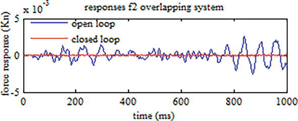
Figure 4.
Centralized non-optimal control system (flour 2).
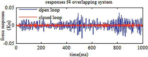
Figure 5.
Centralized non-optimal control system (flour 4).
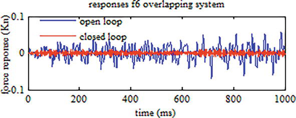
Figure 6.
Centralized non-optimal control system (flour 6).
Then we apply decentralized non-optimal controller for the same floors (Figures 7–10).
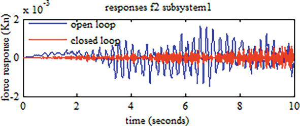
Figure 7.
Decentralized non-0ptimal control sub-system 1(flour 2).
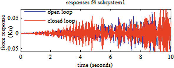
Figure 8.
Decentralized non-optimal control sub-system 1(flour 4).
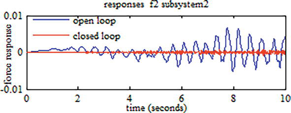
Figure 9.
Decentralized non-optimal control sub-system 2(flour 2).
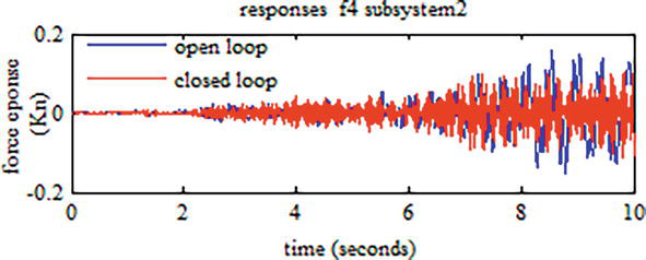
Figure 10.
Decentralized non-optimal control sub-system 2(flour 4).
We notice that in common floor (Figures 8 and 10) the response of system in closed loop form still effective; this is according to the interconnection between subsystems Figure 11.
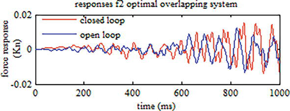
Figure 11.
Centralized optimal control system (flour 2).
An optimization technique was applied for centralized and decentralized controller as show in figure below:
Even when we applied optimization responses in Figure 12 still valuable which may make damages to the building. The cost function of centralized controller is
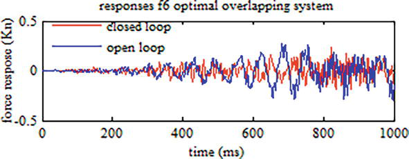
Figure 12.
Centralized optimal control system (flour 6).
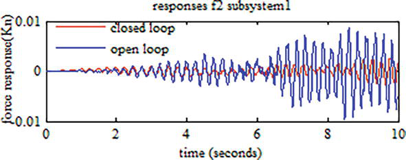
Figure 13.
Decentralized optimal control sub-system 1 (flour 2).
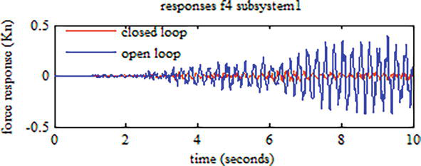
Figure 14.
Decentralized optimal control sub-system 1 (flour 4).
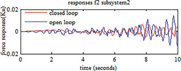
Figure 15.
Decentralized optimal control sub-system 2 (flour 2).
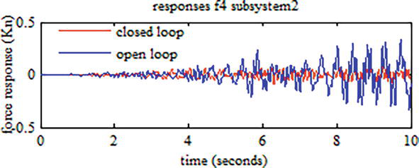
Figure 16.
Decentralized optimal control sub-system 2 (flour 4).
The cost functions of subsystems 1 and 2 are respectively
7. Conclusion
The overlapping decomposition method has been presented in this book chapter, and then the inclusion principle has been introduced to provide a mathematical framework for decentralized control. The inclusion of the cost function has also been discussed to incorporate the optimal control problem for large scale smart building systems where the concept of contractibility of controllers has been discussed. Optimal decentralized dynamic output feedback controllers design has been proposed for six-floor building systems with overlapping structure. Non-optimal overlapping centralized and decentralized controllers are designed for which we found that decentralized controller give better results. Furthermore to improve these results we developed an optimization technique that allow us not just design optimal controller but also minimize the cost function of the whole system for decomposed decentralized (
Acknowledgments
This paper is a summary of final year project’ part for getting research master of M. Z. Doghmane, at the department of electrification (Ex-INH), university of Boumerdes, Algeria.
References
- 1.
Doghmane MZ, Kidouche M, Eladj S, Belahcene B. Design of Optimal Decentralized Controller Using Overlapping Decomposition for smart building system. In: Hatti M, editor. Artificial Intelligence and Renewables Towards an Energy Transition. ICAIRES 2020. Lecture Notes in Networks and Systems. Vol. 174. Tipasa, Algeria: Springer, Cham; 2021. DOI: 10.1007/978-3-030-63846-7_16 - 2.
Mendil C, Kidouche M, Doghmane MZ. Modeling of hydrocarbons rotary drilling systems under torsional vibrations: A survey. In: Hatti M, editor. Artificial Intelligence and Renewables Towards an Energy Transition. ICAIRES 2020. Lecture Notes in Networks and Systems. Vol. 174. Tipasa, Algeria: Springer, Cham; 2021. DOI: 10.1007/978-3-030-63846-7_24 - 3.
Reitherman R, Anagnos T, Meluch W. Building Bridges between Civil Engineers and Science Museums. USA: Consortium of Universities for Research in Earthquake Engineering; 2008 - 4.
Schweier C, Markus M, Steinle E. Simulation of earthquake caused building damages for the development of fast reconnaissance techniques. Natural Hazards and Earth System Sciences. 2004; 2004 (4):285-293 - 5.
Iftar L. Decentralized estimation and control with overlapping input-state output decomposition. Automatica. 1993; 29 :511-516 - 6.
Doghmane MZ, Kidouche M, Ahriche A. Decentralized overlapping control design with application to rotary drilling system. IETE Journal of Research. 2021. DOI: 10.1080/03772063.2021.1886602 - 7.
Bakule L, Lunze J. Decentralized Design of Feedback Control for Large-Scale Systems. Priloha casopisu Kybernetika, Supplement to the journal Kyberneitika: ACADEMIA, praha; 1988 - 8.
Mendil C, Kidouche M, Doghmane MZ. A study of the parametric variations influences on stick-slip vibrations in smart rotary drilling systems. In: Hatti M, editor. Artificial Intelligence and Renewables Towards an Energy Transition. ICAIRES 2020. Lecture Notes in Networks and Systems. Vol. 174. Tipasa, Algeria: Springer, Cham; 2021. DOI: 10.1007/978-3-030-63846-7_67 - 9.
Ikeda M, Siljack DD. Overlapping decentralized control with input, state, and output inclusion. Control Theory and Advanced Technology. 1986; 2 (2):155-172 - 10.
Palacios-Quinonero F, Rodellar J, Rosell JM. Sequential design of multi-overlapping controllers for longitudinal multi-overlapping systems. Applied Mathematics and Computation. 2010; 217 (3):1170-1183 - 11.
Mendil C, Kidouche M, Doghmane MZ. Automatic control of a heat exchanger in a nuclear power station: The classical and the fuzzy methods. International Conference on Advanced Electrical Engineering (ICAEE). 2019; 2019 :1-6. DOI: 10.1109/ICAEE47123.2019.9014661